ELECTRIC VEHICLE CONVERTER REMOVAL

CAUTION / NOTICE / HINT
The necessary procedures (adjustment, calibration, initialization, or registration) that must be performed after parts are removed and installed, or replaced during HV converter kit removal/installation are shown below.
| Replaced Part or Performed Procedure | Necessary Procedures | Effect/Inoperative Function when Necessary Procedure not Performed | Link |
|---|---|---|---|
| Auxiliary battery terminal is disconnected/reconnected | Memorize steering angle neutral point | Lane departure alert system (w/ Steering Control) | |
| Intelligent clearance sonar system*1 | |||
| Simple intelligent parking assist system*1 | |||
| Pre-crash safety system | |||
| Adaptive high beam system | |||
| Parking assist monitor system | |||
| Initialize back door lock | Power door lock control system | ||
| Replacement of inverter with converter assembly | Resolver learning |
|
|
for SFI system (w/ Canister Pump Module) |
Perform Vehicle Identification Number (VIN) registration | MIL comes on | |
for SFI system (w/o Canister Pump Module) |
Perform Vehicle Identification Number (VIN) or frame number registration | MIL comes on |
Click here Click here
CAUTION:
-
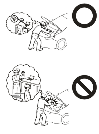
Orange wire harnesses and connectors indicate high-voltage circuits. To prevent electric shock, always follow the procedure described in the repair manual.
-

To prevent electric shock, wear insulated gloves when working on wire harnesses and components of the high voltage system.
Note
-
If metal shavings are created when bolts are removed from the inverter with converter assembly, remove them using tape or equivalent.
-
Use non-residue type tape.
PROCEDURE
-
REMOVE INVERTER WITH CONVERTER ASSEMBLY
-
REMOVE NO. 1 INVERTER BRACKET
-
REMOVE NO. 2 INVERTER BRACKET
-
REMOVE WIRE HARNESS CLAMP BRACKET (w/o Canister Pump Module)
-
REMOVE WIRE HARNESS CLAMP BRACKET (w/ Canister Pump Module)
-
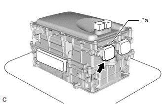
VERIFY THAT VOLTAGE OF INVERTER WITH CONVERTER IS 0 V
CAUTION:
Be sure to wear insulated gloves.
Note
Do not allow any foreign matter or water to enter the inverter with converter assembly.
-
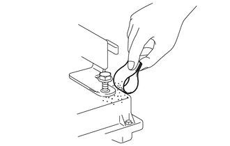
*a Tape Remove the protective tape from the HV floor under wire opening.
-
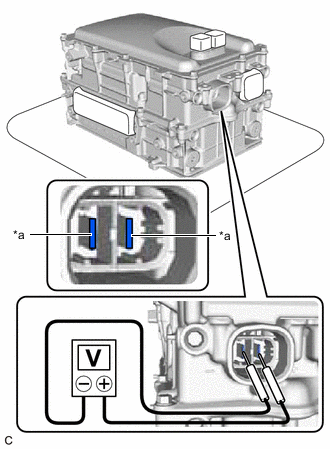
*a Voltage Measurement Position Using a voltmeter, measure the voltage between the high voltage cable connector terminals.
Standard voltage 0V Tech Tips
-
Use measuring range of DC 750 V or more on the voltmeter.
-
If it is confirmed that high-voltage is not being applied to the inverter with converter assembly, the following procedures can be performed without using insulated tools or gloves.
-
-
Apply protective tape to the area that was exposed.
Note
Use non-residue type tape.
-
-
CLEAN INVERTER WITH CONVERTER ASSEMBLY
-
Using a piece of cloth, clean the outside of the inverter with converter assembly and around the bolts.
Note
To prevent foreign matter from entering the inverter with converter assembly, make sure that the protective tape is not partially removed.
-
-
HOW TO PREVENT STATIC ELECTRICITY
- SST
- 09890-47010
Note
-
Static electricity should be eliminated when removing/installing the inverter with converter assembly.
-
Do not touch the electronic components of a circuit board.
-
Keep clothes away from electronic components.
-
Place the inverter with converter assembly and any removed electronic components on SST (antistatic mat).
-
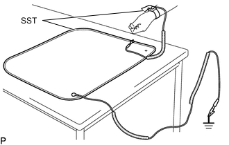
Wear an antistatic wrist strap.
-
Connect the ground clip of the antistatic mat securely to a ground point provided in the workshop or on a workbench (anchor bolt).
Tech Tips
If the ground clip cable is too short, use an extension cable.
-
Connect the ground clip of the antistatic wrist strap securely to the specified point of the antistatic mat.
-
When handling internal components of the inverter with converter assembly, use only antistatic gloves or bare hands to prevent damage from static electricity or the entry of foreign matter.
-
DRAIN COOLANT (for Inverter)
-
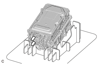
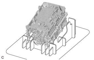
Place the inverter with converter assembly on a stand as shown in the illustration.
Note
-
Make sure to use the stand, otherwise the low voltage connectors or inverter upper cover may be damaged.
-
Make sure to place the inverter with converter assembly on the stand so that the coolant pipes are positioned downward.
-
-
Connect the ground clip of the antistatic wrist strap securely to the inverter with converter assembly.
-
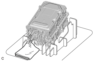
Remove the 2 caps from the coolant pipes and drain the coolant (for inverter).
-
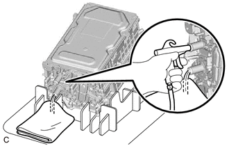
Blow compressed air into the inverter with converter assembly until most all of the coolant (for inverter) is blown out.
Note
-
Do not damage the coolant pipes.
-
Apply compressed air to the silver colored coolant pipe.
Tech Tips
-
Use a piece of cloth as shown in the illustration to prevent the coolant (for inverter) from spraying.
-
Cover the air inlet port with a piece of cloth to minimize air leakage.
-
Install the 2 caps to the coolant pipes.
-
-
-
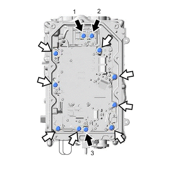
REMOVE CONVERTER COVER
-
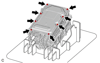
Remove the 8 bolts.
-
Using a screwdriver with its tip wrapped with protective tape, remove the converter cover from the inverter with converter assembly.
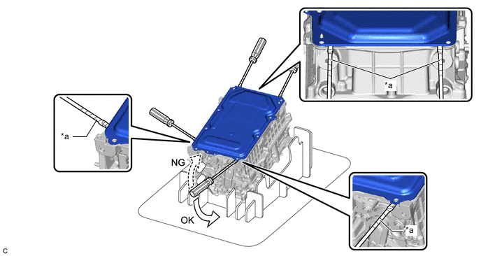
*a Protective Tape - - Note
-
Do not damage the sealing surfaces of the inverter with converter assembly.
-
Do not touch or allow grease or oil to contact the sealing surfaces of the inverter with converter assembly.
-
Be careful not to damage the sealing surfaces of the inverter with converter assembly.
-
To prevent internal components of the inverter with converter assembly from being damaged, do not insert the screwdriver excessively.
-
-
-
REMOVE SEAL PACKING FROM INVERTER WITH CONVERTER ASSEMBLY
Note
-
Do not allow any removed seal packing to enter the inverter with converter assembly.
-
Do not touch the circuit board.
-
Do not allow any moisture to come into contact.
-
Using a finger, remove any seal packing that has seeped into the inverter with converter assembly.
Tech Tips
Make sure to remove any seal packing which has seeped toward the inside of inverter with converter assembly before installing the seal packing removal cover, otherwise the seal packing may be pushed into the inverter with converter assembly.
-
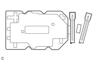
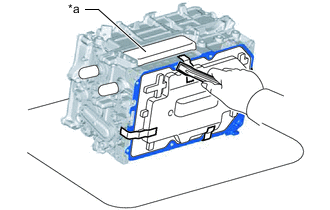
Break off the seal packing removal cover and scraper at each break off line.
-
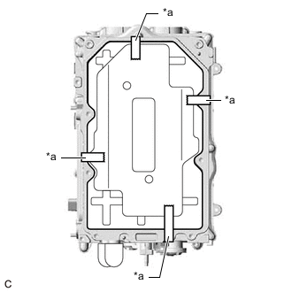
*a Tape Set the seal packing removal cover on the inverter with converter assembly and secure it with tape.
Note
Make sure that the seal packing removal cover is in secure contact with the inside surface of the inverter with converter assembly without any gaps.
-
*a MG Connector Opening Place the inverter with converter assembly on its side on an antistatic mat as shown in the illustration.
Note
-
Make sure that the MG connector opening in the inverter with converter assembly is facing upward.
-
Make sure that the inverter with converter assembly is oriented correctly, otherwise seal packing may enter the inverter with converter assembly.
-
-
Using a scraper, remove any remaining seal packing from the inverter with converter assembly.
Note
-
It is not necessary to remove small amounts of seal packing which are not easily scraped off.
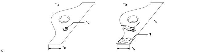
*a Correct *b Incorrect *c Width of Sealing Surface *d Difficult to Remove Seal Packing *e Peeled Off Seal Packing *f Seal Packing Remaining on Full Width of Sealing Surface -
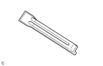
Make sure to use the scraper supplied with the seal packing removal cover.
Tech Tips
Use the small end of the scraper to remove seal packing from small areas such as bolt holes.
-
-
Remove the tape used to secure the seal packing removal cover and then remove any seal packing which was under the tape.
-
Using a clean piece of cloth, clean the sealing surfaces of the inverter with converter assembly.
Note
-
Do not use compressed air or a vacuum cleaner to clean the sealing surfaces of the inverter with converter assembly.
-
Do not use non-residue solvent to clean the sealing surfaces of the inverter with converter assembly.
-
-
Remove the seal packing removal cover.
Note
Make sure that the inverter with converter assembly is oriented correctly, otherwise seal packing may enter the inverter with converter assembly when removing the seal packing removal cover.
-
Make sure that the inverter with converter assembly is free of foreign matter.
-
-
REMOVE HV CONVERTER KIT
Note
-
Do not touch the circuit board.
-
Do not allow any foreign matter or water to enter the inverter with converter assembly.
-
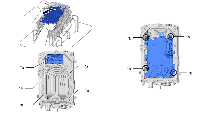
Place the inverter with converter assembly on a stand as shown in the illustration.
Note
Make sure that the inverter with converter assembly is oriented correctly.
-

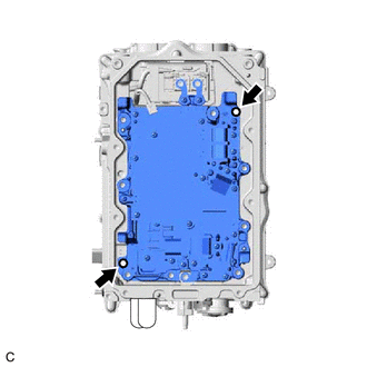
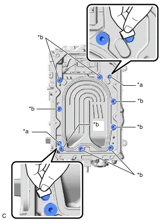
Bolt (A) 
Bolt (B) Remove the 3 bolts (A) in the order shown in the illustration.
-
Remove the 8 bolts (B).
-
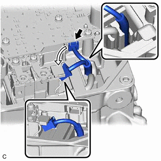
Disconnect the HV converter kit connector and set it as shown in the illustration.
Note
Make sure that the wire harness of the connector is engaged to the filter condenser.
-
Install 2 HV converter kit installation bolts at the positions shown in the illustration and tighten them in several steps to separate the HV converter kit from the inverter with converter assembly.
Note
-
Tighten the 2 bolts in several steps.
-
Do not forcibly separate the HV converter kit.
-
In order to prevent any foreign matter from entering the inverter with converter assembly, do not remove the bolts.
-
-
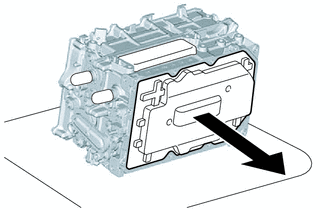
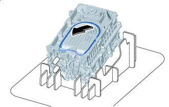
Hold the corners of the HV converter kit and remove it as shown in the illustration.
*a Do Not Allow Coolant (for Inverter) to Enter *b Hold Here Remove in this Direction - - CAUTION:
-
As there is a coolant passage underneath the HV converter kit, be careful not to spill any coolant (for inverter) into the filter condenser or the holes around the edge of the inverter with converter assembly.
-
If any coolant (for inverter) spills into the filter condenser or the holes around the edge of the inverter with converter assembly, do not reuse the inverter with converter assembly.
-
If any coolant (for inverter) spills onto any area other than the specified areas, remove it with a clean piece of cloth.
-
-
*a Bolt Contacting Surface *b Bolt Hole Remove any metal shavings from the areas around the bolt holes and 2 positions where bolts were installed to separate the HV converter kit, using tape or equivalent.
-
Remove in this Direction Using a clean scraper, lift the O-ring at the position shown in the illustration and then remove it.
CAUTION:
-
When removing the O-ring, be careful not to spill any coolant (for inverter) into the filter condenser or the holes around the edge of the inverter with converter assembly.
-
If any coolant (for inverter) spills into the filter condenser or the holes around the edge of the inverter with converter assembly, do not reuse the inverter with converter assembly.
-
If any coolant (for inverter) spills onto any area other than the filter condenser or the holes around the edge of the inverter with converter assembly, remove it with a clean piece of cloth.
-
-
Clean the O-ring groove of the inverter with converter assembly.
Note
Make sure that the O-ring groove and coolant passage of the inverter with converter assembly are free of foreign matter.
-