INVERTER WITH CONVERTER INSTALLATION
PROCEDURE
-
INSTALL WIRE HARNESS CLAMP BRACKET (w/o Canister Pump Module)
-
Install the wire harness clamp bracket to the inverter with converter assembly with the bolt.
- Torque:
- 8.0 N*m { 82 kgf*cm, 71 in.*lbf }
-
Install the wire harness clamp bracket to the inverter with converter assembly with the bolt.
- Torque:
- 8.0 N*m { 82 kgf*cm, 71 in.*lbf }
-
Install the 2 wire harness clamp brackets to the inverter with converter assembly with the 2 bolts.
- Torque:
- 8.0 N*m { 82 kgf*cm, 71 in.*lbf }
-
-
INSTALL WIRE HARNESS CLAMP BRACKET (w/ Canister Pump Module)
-
Install the wire harness clamp bracket to the inverter with converter assembly with the 2 bolts.
- Torque:
- 8.0 N*m { 82 kgf*cm, 71 in.*lbf }
-
Install the wire harness clamp bracket to the inverter with converter assembly with the bolt.
- Torque:
- 8.0 N*m { 82 kgf*cm, 71 in.*lbf }
-
Install the 2 wire harness clamp brackets to the inverter with converter assembly with the 2 bolts.
- Torque:
- 8.0 N*m { 82 kgf*cm, 71 in.*lbf }
-
-
INSTALL NO. 2 INVERTER BRACKET
-
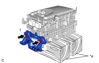
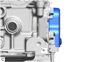
*a Wooden Block Set the inverter with converter assembly on wooden blocks.
Note
Make sure to support the inverter with converter assembly at the positions shown in the illustration, otherwise it may be damaged.
-
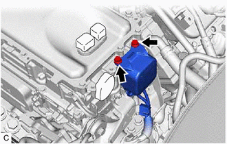
Temporarily install the No. 2 inverter bracket to the inverter with converter assembly with the 2 bolts.
-
Fully tighten the 2 bolts in the order shown in the illustration.
- Torque:
- 15 N*m { 153 kgf*cm, 11 ft.*lbf }
-
-
INSTALL NO. 1 INVERTER BRACKET
-
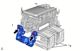
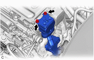
*a Wooden Block Temporarily install the No. 1 inverter bracket to the inverter with converter assembly with the 2 bolts.
-
Fully tighten the 2 bolts in the order shown in the illustration.
- Torque:
- 15 N*m { 153 kgf*cm, 11 ft.*lbf }
-
-
INSTALL INVERTER WITH CONVERTER ASSEMBLY
CAUTION:
Wear insulated gloves.
-
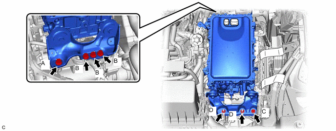
Temporarily install the inverter with converter assembly with the 5 bolts and 2 nuts.
Note
-
When installing the inverter with converter assembly, be careful not to damage the parts around it.
-
To prevent damage, do not hold the inverter with converter assembly by the connectors, brackets or cooling pipes.
-
To prevent damage due to static electricity, do not touch the terminals of the disconnected connectors.
-
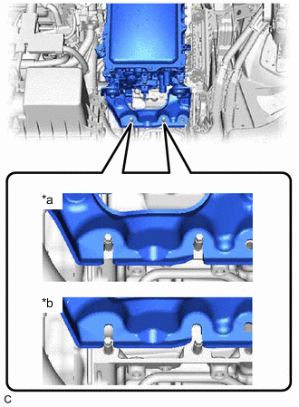
*a Correct *b Incorrect Make sure that the inverter with converter assembly is positioned so that the stud bolts are in contact with the base of the U-shaped portions of the No. 1 inverter bracket.
Tech Tips
If the bolts and nuts are not tightened appropriately, the inverter with converter assembly may make an abnormal noise.
-
-
Fully tighten the bolt (A).
- Torque:
- 25 N*m { 255 kgf*cm, 18 ft.*lbf }
-
Fully tighten the 3 bolts (B).
- Torque:
- 25 N*m { 255 kgf*cm, 18 ft.*lbf }
-
Fully tighten the bolt (C).
- Torque:
- 25 N*m { 255 kgf*cm, 18 ft.*lbf }
-
Fully tighten the 2 nuts (D).
- Torque:
- 25 N*m { 255 kgf*cm, 18 ft.*lbf }
-
-
CONNECT MOTOR CABLE
CAUTION:
Wear insulated gloves.
Note
Do not allow any foreign matter or water to enter the inverter with converter assembly.
-
Temporarily connect the motor cable to the inverter with converter assembly with the 4 bolts.
Note
-
Do not touch the waterproof seal or terminals of the connector.
-
Do not damage the terminals, connector housing or inverter with converter assembly during disconnection.
-
-
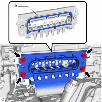
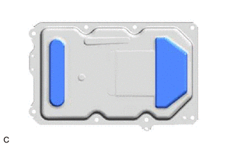
*a Waterproof Seal Fully tighten the bolt (A).
- Torque:
- 8.0 N*m { 82 kgf*cm, 71 in.*lbf }
-
Fully tighten the 3 bolts in the order shown in the illustration to connect the motor cable to the inverter with converter assembly.
- Torque:
- 8.0 N*m { 82 kgf*cm, 71 in.*lbf }
-
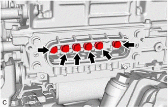
Temporarily install the 6 bolts.
Note
-
To prevent the threads from being damaged, temporarily tighten the 6 bolts by hand.
-
Do not damage the terminals, connector housing or inverter with converter assembly during disconnection.
-
-
Using an insulated tool, fully tighten the 6 bolts.
- Torque:
- 8.0 N*m { 82 kgf*cm, 71 in.*lbf }
Note
-
Do not touch the waterproof seal or terminals of the connector.
-
Do not damage the terminals, connector housing or inverter with converter assembly during disconnection.
-
Be sure to use a torque wrench to tighten the bolts.
-
-
INSTALL INVERTER COVER
CAUTION:
Wear insulated gloves.
-
Install the inverter cover to the inverter with converter assembly with the 2 bolts.
- Torque:
- 8.0 N*m { 82 kgf*cm, 71 in.*lbf }
Note
-
Visually confirm that the inverter cover waterproof seal is securely installed before installing the inverter cover.
-
Do not touch the waterproof seal of the inverter cover.
-
Make sure that the interlock is fully engaged.
-
Do not damage the terminals, interlock connector or inverter with converter assembly during installation.
-
Do not allow any foreign matter or water to enter the inverter with converter assembly.
-
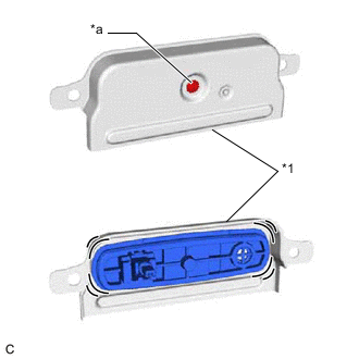
*1 Inverter Cover *a Screw Do not remove or excessively tighten the screw of the inverter cover.
-
Although the inverter cover may feel loose, this is not due to a malfunction.
-
*a No Gap Push in the inverter cover until it contacts the inverter with converter assembly.
-
-
CONNECT INLET NO. 1 INVERTER COOLING HOSE
-
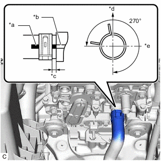
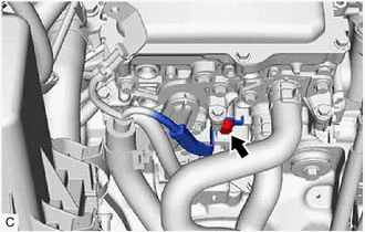
*a Alignment Mark (Light Blue) *b Rib *c 2 to 11 mm (0.0787 to 0.433 in.) *d Up *e LH Side Connect the inlet No. 1 inverter cooling hose to the inverter with converter assembly and slide the clip to secure it.
Note
To prevent foreign matter from entering the inverter with converter assembly and inverter cooling system, do not remove the pieces of cloth from the pipe and disconnected hose until installation.
Tech Tips
-
Make sure that the clip is positioned as shown in the illustration.
-
Make sure to align the alignment mark of the hose with the rib of the inverter with converter assembly.
-
-
-
CONNECT OUTLET NO. 1 INVERTER COOLING HOSE
-
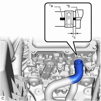
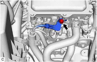
*a Alignment Mark (Pink) *b Rib *c 2 to 11 mm (0.0787 to 0.433 in.) Connect the outlet No. 1 inverter cooling hose to the inverter with converter assembly and slide the clip to secure it.
Note
To prevent foreign matter from entering the inverter with converter assembly and inverter cooling system, do not remove the pieces of cloth from the pipe and disconnected hose until installation.
Tech Tips
-
Make sure that the clip is positioned as shown in the illustration.
-
Make sure to align the alignment mark of the hose with the rib of the inverter with converter assembly.
-
-
-
CONNECT NO. 3 ENGINE WIRE
CAUTION:
Wear insulated gloves.
-
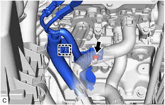
Engage the clamp and connect the No. 3 engine wire to the inverter with converter assembly.
-
Temporarily install the nut.
Note
To prevent the threads from being damaged, temporarily tighten the nut by hand.
-
Fully tighten the nut.
- Torque:
- 8.0 N*m { 82 kgf*cm, 71 in.*lbf }
-
Engage the 2 claws to close the No. 3 engine wire terminal cover.
-
Connect the No. 3 engine wire to the inverter with converter assembly with the bolt.
- Torque:
- 8.5 N*m { 87 kgf*cm, 75 in.*lbf }
-
Connect the No. 3 engine wire to the inverter with converter assembly with the bolt.
- Torque:
- 8.5 N*m { 87 kgf*cm, 75 in.*lbf }
-
-
INSTALL WIRE HARNESS CLAMP BRACKET
-
Install the wire harness clamp bracket to the inverter with converter assembly with the nut.
- Torque:
- 8.0 N*m { 82 kgf*cm, 71 in.*lbf }
-
-
CONNECT AIR CONDITIONING WIRE
CAUTION:
Wear insulated gloves.
-
Engage the clamp.
-
Connect the air conditioning wire to the inverter with converter assembly and install the 2 bolts.
- Torque:
- 8.0 N*m { 82 kgf*cm, 71 in.*lbf }
Note
-
Do not allow any foreign matter or water to enter the inverter with converter assembly.
-
Do not touch the waterproof seal or terminals of the connector.
-
Do not damage the terminals, connector housing or inverter with converter assembly when connecting the connector.
-
-
CONNECT HV FLOOR UNDER WIRE
CAUTION:
Wear insulated gloves.
-
Engage the 2 clamps.
-
Connect the HV floor under wire to the inverter with converter assembly and install the 2 bolts.
- Torque:
- 8.0 N*m { 82 kgf*cm, 71 in.*lbf }
Note
-
Do not allow any foreign matter or water to enter the inverter with converter assembly.
-
Do not touch the waterproof seal or terminals of the connector.
-
Do not damage the terminals, connector housing or inverter with converter assembly when connecting the connector.
-
-
CONNECT ENGINE WIRE (w/o Canister Pump Module)
CAUTION:
Wear insulated gloves.
Note
Do not allow any foreign matter or water to enter the inverter with converter assembly.
-
Engage the 2 clamps to connect the engine wire.
-
Install the bolt.
- Torque:
- 8.0 N*m { 82 kgf*cm, 71 in.*lbf }
-
Install the inverter protector to the inverter with converter assembly with the bolt.
- Torque:
- 9.5 N*m { 97 kgf*cm, 84 in.*lbf }
-
Engage the 2 clamps.
-
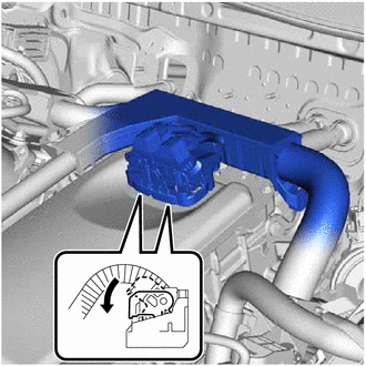
Connect the 2 inverter with converter assembly connectors and move each lock lever as shown in the illustration.
Note
-
To prevent damage due to static electricity, do not touch the terminals of the disconnected connectors.
-
Do not damage the terminals, connector housing or inverter with converter assembly when connecting the connectors.
-
Do not touch the waterproof seal or terminals of the connectors.
-
-
Engage the 2 claws.
-
Connect the 3 No. 1 engine room relay block and No. 1 junction block assembly connectors.
-
Install the No. 1 relay block cover.
-
-
CONNECT ENGINE WIRE (w/ Canister Pump Module)
CAUTION:
Wear insulated gloves.
Note
Do not allow any foreign matter or water to enter the inverter with converter assembly.
-
Engage the 2 clamps to connect the engine wire.
-
Install the bolt.
- Torque:
- 8.0 N*m { 82 kgf*cm, 71 in.*lbf }
-
Install the inverter protector to the inverter with converter assembly with the bolt.
- Torque:
- 9.5 N*m { 97 kgf*cm, 84 in.*lbf }
-
Engage the 2 clamps.
-
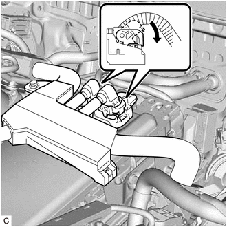
Connect the 2 inverter with converter assembly connectors and move each lock lever as shown in the illustration.
Note
-
To prevent damage due to static electricity, do not touch the terminals of the disconnected connectors.
-
Do not damage the terminals, connector housing or inverter with converter assembly when connecting the connectors.
-
Do not touch the waterproof seal or terminals of the connectors.
-
-
Engage the 2 claws.
-
Connect the 3 No. 1 engine room relay block and No. 1 junction block assembly connectors.
-
Install the No. 1 relay block cover.
-
-
INSTALL BATTERY CLAMP SUB-ASSEMBLY
-
Install the battery clamp sub-assembly with the 3 bolts.
- Torque:
- 15.4 N*m { 157 kgf*cm, 11 ft.*lbf }
-
-
INSTALL ECM
-
INSTALL OUTER COWL TOP PANEL SUB-ASSEMBLY
-
INSTALL COWL BODY MOUNTING REINFORCEMENT LH
-
INSTALL WATER GUARD PLATE
-
INSTALL NO. 1 HEATER AIR DUCT SPLASH SHIELD SEAL (for LHD)
-
INSTALL NO. 2 HEATER AIR DUCT SPLASH SHIELD SEAL (for RHD)
-
INSTALL WINDSHIELD WIPER MOTOR AND LINK ASSEMBLY
-
INSTALL NO. 1 ENGINE COVER SUB-ASSEMBLY
-
INSTALL SERVICE PLUG GRIP
-
INSTALL AUXILIARY BATTERY
-
CONNECT ENGINE WIRE
-
Connect the battery state sensor assembly connector.
-
Engage the 2 claws to connect the engine wire to the battery current sensor holder.
-
-
ADD COOLANT (for Inverter)
-
INSPECT FOR COOLANT LEAK (for Inverter)
-
INSTALL REAR ENGINE UNDER COVER LH
-
PERFORM RESOLVER LEARNING