INVERTER WITH CONVERTER REMOVAL
CAUTION / NOTICE / HINT
The necessary procedures (adjustment, calibration, initialization, or registration) that must be performed after parts are removed and installed, or replaced during inverter with converter assembly removal/installation are shown below.
| Replaced Part or Performed Procedure | Necessary Procedures | Effect/Inoperative Function when Necessary Procedure not Performed | Link |
|---|---|---|---|
| Auxiliary battery terminal is disconnected/reconnected | Memorize steering angle neutral point | Lane departure alert system (w/ Steering Control) | |
| Intelligent clearance sonar system*1 | |||
| Simple intelligent parking assist system*1 | |||
| Pre-crash safety system | |||
| Adaptive high beam system | |||
| Parking assist monitor system | |||
| Initialize back door lock | Power door lock control system | ||
| Replacement of inverter with converter assembly | Resolver learning |
|
|
for SFI system (w/ Canister Pump Module) |
Perform Vehicle Identification Number (VIN) registration | MIL comes on | |
for SFI system (w/o Canister Pump Module) |
Perform Vehicle Identification Number (VIN) or frame number registration | MIL comes on |
Click here Click here
CAUTION:
-
Orange wire harnesses and connectors indicate high-voltage circuits. To prevent electric shock, always follow the procedure described in the repair manual.
-

To prevent electric shock, wear insulated gloves when working on wire harnesses and components of the high voltage system.
PROCEDURE
-
PRECAUTION
Note
After turning the power switch off, waiting time may be required before disconnecting the cable from the negative (-) auxiliary battery terminal. Therefore, make sure to read the disconnecting the cable from the negative (-) auxiliary battery terminal notices before proceeding with work.
-
DISCONNECT ENGINE WIRE
-
Disengage the 2 claws and disconnect the engine wire from the battery current sensor holder.
-
Disconnect the battery state sensor assembly connector.
-
-
REMOVE AUXILIARY BATTERY
-
REMOVE SERVICE PLUG GRIP
-
REMOVE REAR ENGINE UNDER COVER LH
-
DRAIN COOLANT (for Inverter)
-
REMOVE NO. 1 ENGINE COVER SUB-ASSEMBLY
-
REMOVE WINDSHIELD WIPER MOTOR AND LINK ASSEMBLY
-
REMOVE NO. 1 HEATER AIR DUCT SPLASH SHIELD SEAL (for LHD)
-
REMOVE NO. 2 HEATER AIR DUCT SPLASH SHIELD SEAL (for RHD)
-
REMOVE WATER GUARD PLATE
-
REMOVE COWL BODY MOUNTING REINFORCEMENT LH
-
REMOVE OUTER COWL TOP PANEL SUB-ASSEMBLY
-
REMOVE ECM
-
REMOVE BATTERY CLAMP SUB-ASSEMBLY
-
Remove the 3 bolts and battery clamp sub-assembly.
-
-
DISCONNECT ENGINE WIRE (w/o Canister Pump Module)
CAUTION:
Wear insulated gloves.
Note
Do not allow any foreign matter or water to enter the inverter with converter assembly.
-
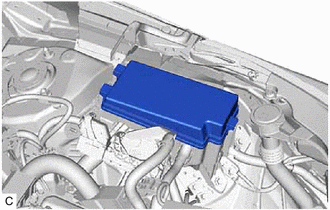
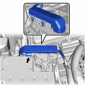
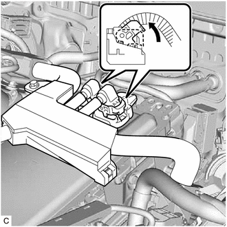
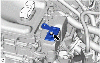
Remove the No. 1 relay block cover.
-
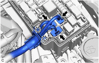
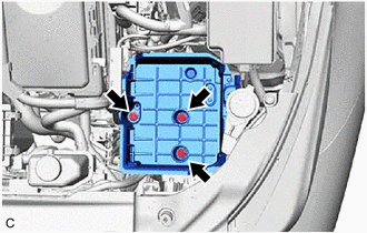
Disconnect the 3 No. 1 engine room relay block and No. 1 junction block assembly connectors.
-
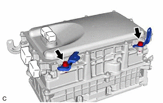
Disengage the 2 claws.
-
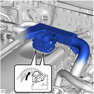
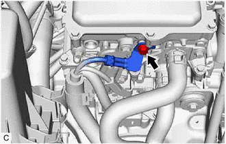
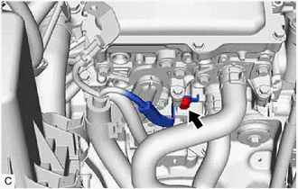
Move each lock lever as shown in the illustration and disconnect the 2 inverter with converter assembly connectors.
Note
-
Do not damage the terminals, connector housing or inverter with converter assembly during disconnection.
-
Cover the hole where the cable was connected with tape (non-residue type) or equivalent to prevent entry of foreign matter.
-
Do not allow any foreign matter or water to enter the inverter with converter assembly.
-
Insulate the disconnected terminals with insulating tape.
-
Do not touch the waterproof seal or terminals of the connector.
-
-
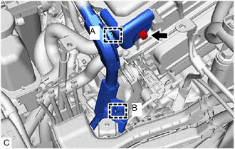
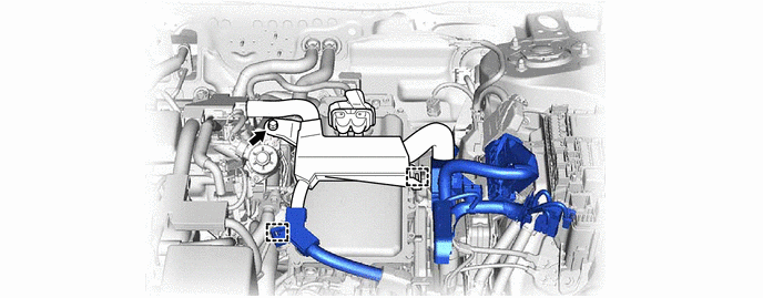
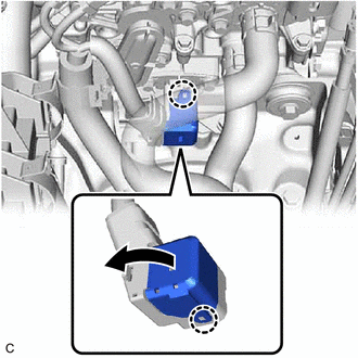
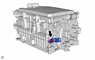
Remove the bolt.
-
Disengage the clamp (A) and remove the inverter protector.
-
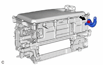
Disengage the clamp (B).
-
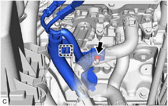
Remove the bolt.
-
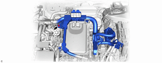
Disengage the 2 clamps and disconnect the engine wire.
-
-
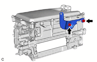
DISCONNECT ENGINE WIRE (w/ Canister Pump Module)
CAUTION:
Wear insulated gloves.
Note
Do not allow any foreign matter or water to enter the inverter with converter assembly.
-
Remove the No. 1 relay block cover.
-
Disconnect the 3 No. 1 engine room relay block and No. 1 junction block assembly connectors.
-
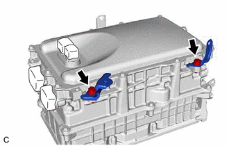
Disengage the 2 claws.
-
Move each lock lever as shown in the illustration and disconnect the 2 inverter with converter assembly connectors.
Note
-
Do not damage the terminals, connector housing or inverter with converter assembly during disconnection.
-
Cover the hole where the cable was connected with tape (non-residue type) or equivalent to prevent entry of foreign matter.
-
Do not allow any foreign matter or water to enter the inverter with converter assembly.
-
Insulate the disconnected terminals with insulating tape.
-
Do not touch the waterproof seal or terminals of the connector.
-
-
Remove the bolt.
-
Disengage the clamp (A) and remove the inverter protector.
-
Disengage the clamp (B).
-
Remove the bolt.
-
Disengage the 2 clamps and disconnect the engine wire.
-
-
REMOVE CONNECTOR COVER ASSEMBLY
CAUTION:
Wear insulated gloves.
-
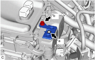
*a Bolt (A) *b Bolt (B) Remove the bolt (B).
-
Using a T25 "TORX" socket wrench, remove the bolt (A) and connector cover assembly from the inverter with converter assembly.
Note
-
Do not touch the connector cover assembly waterproof seal.
-
Do not allow any foreign matter or water to enter the inverter with converter assembly.
-
-
-
CHECK TERMINAL VOLTAGE
CAUTION:
Wear insulated gloves.
Note
Do not allow any foreign matter or water to enter the inverter with converter assembly.
-
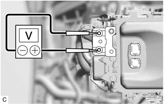
Using a voltmeter, measure the voltage between the terminals of the 2 phase connectors.
Standard Voltage 0 V Tech Tips
Use a measuring range of DC 750 V or more on the voltmeter.
-
-
TEMPORARILY INSTALL CONNECTOR COVER ASSEMBLY
CAUTION:
Wear insulated gloves.
-
Temporarily install the connector cover assembly to the inverter with converter assembly.
-
Using a T25 "TORX" socket wrench, install the bolt.
- Torque:
- 4.5 N*m { 46 kgf*cm, 40 in.*lbf }
Note
Do not touch the waterproof seal of the connector cover assembly.
-
-
DISCONNECT HV FLOOR UNDER WIRE
CAUTION:
Wear insulated gloves.
Note
Do not allow any foreign matter or water to enter the inverter with converter assembly.
-
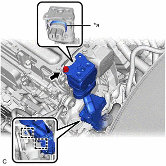
*a Waterproof Seal Remove the bolt and disconnect the HV floor under wire from the inverter with converter assembly.
Note
-
Do not touch the waterproof seal or terminals of the connector.
-
Do not damage the terminals, connector housing or inverter with converter assembly during disconnection.
-
Cover the hole where the cable was connected with tape (non-residue type) or equivalent to prevent entry of foreign matter.
-
Do not allow any foreign matter or water to enter the inverter with converter assembly.
-
Insulate the disconnected terminals with insulating tape.
-
-
Disengage the 2 clamps.
-
-
DISCONNECT AIR CONDITIONING WIRE
CAUTION:
Wear insulated gloves.
-
*a Waterproof Seal Remove the 2 bolts and disconnect the air conditioning wire from the inverter with converter assembly.
Note
-
Do not touch the waterproof seal or terminals of the connector.
-
Do not damage the terminals, connector housing or inverter with converter assembly during disconnection.
-
Cover the hole where the cable was connected with tape (non-residue type) or equivalent to prevent entry of foreign matter.
-
Do not allow any foreign matter or water to enter the inverter with converter assembly.
-
Insulate the disconnected terminals with insulating tape.
-
-
Disengage the clamp.
-
-
REMOVE WIRE HARNESS CLAMP BRACKET
-
Remove the nut and wire harness clamp bracket.
-
-
DISCONNECT NO. 3 ENGINE WIRE
CAUTION:
Wear insulated gloves.
-
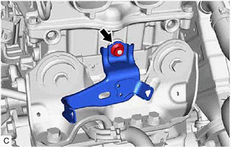
Remove the bolt.
-
Remove the bolt.
-
Disengage the 2 claws and open the No. 3 engine wire terminal cover.
-
Remove the nut.
-
Disengage the clamp and disconnect the No. 3 engine wire from the inverter with converter assembly.
-
-
DISCONNECT OUTLET NO. 1 INVERTER COOLING HOSE
-
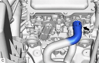
Slide the clip and disconnect the outlet No. 1 inverter cooling hose from the inverter with converter assembly.
Note
Put pieces of cloth into the pipe and disconnected hose or cover the pipe and hose with plastic bags to prevent entry of foreign matter.
-
-
DISCONNECT INLET NO. 1 INVERTER COOLING HOSE
-
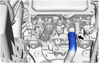
Slide the clip and disconnect the inlet No. 1 inverter cooling hose from the inverter with converter assembly.
Note
Put pieces of cloth into the pipe and disconnected hose or cover the pipe and hose with plastic bags to prevent entry of foreign matter.
-
-
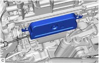
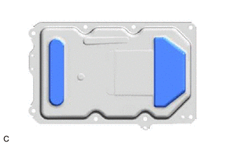
REMOVE INVERTER COVER
CAUTION:
Wear insulated gloves.
-
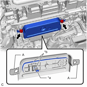
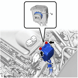
*a Interlock *b Waterproof Seal Remove the 2 bolts and inverter cover from the inverter with converter assembly.
Note
-
Make sure to pull the inverter cover straight out, as a connector is connected to the inside of the inverter cover.
-
Do not touch the waterproof seal of the inverter cover.
-
Do not allow any foreign matter or water to enter the inverter with converter assembly.
-
When removing the inverter cover, do not pull the areas (A) as they may deform.
-
Make sure that the interlock is installed to the inverter cover.
-
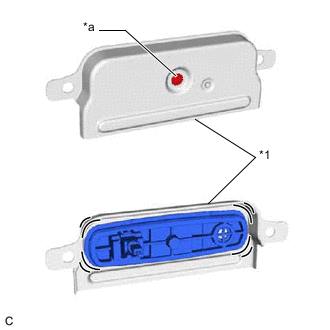
*1 Inverter Cover *a Screw Do not remove or excessively tighten the screw of the inverter cover.
-
Although the inverter cover may feel loose, this is not due to a malfunction.
Tech Tips
If necessary, use a screwdriver with its tip wrapped with protective tape as shown in the illustration to remove the inverter cover.
-
-
-
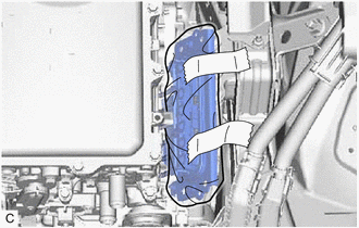
DISCONNECT MOTOR CABLE
CAUTION:
Wear insulated gloves.
-
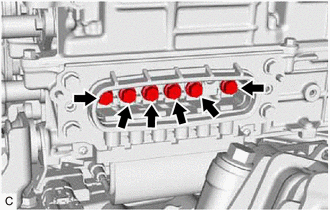
Using an insulated tool, remove the 6 bolts.
Note
-
Do not allow any foreign matter or water to enter the inverter with converter assembly.
-
Do not touch the waterproof seal or terminals of the connector.
-
-
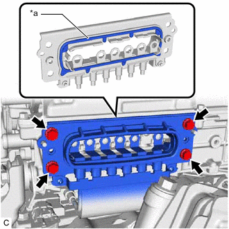
*a Waterproof Seal Remove the 4 bolts and disconnect the motor cable from the inverter with converter assembly.
Note
-
Do not allow any foreign matter or water to enter the inverter with converter assembly.
-
Do not touch the waterproof seal or terminals of the connector.
-
Do not damage the terminals, connector housing or inverter with converter assembly during disconnection.
-
Insulate the disconnected terminals with insulating tape.
-
After disconnecting the motor cable, wrap it with a plastic bag or equivalent to protect it.
-
Cover the hole where the cable was connected with tape (non-residue type) or equivalent to prevent entry of foreign matter.
-
To prevent the wire harness from being caught, make sure to bundle the wire harness using insulating tape or equivalent.
-
-
-
REMOVE INVERTER WITH CONVERTER ASSEMBLY
CAUTION:
Wear insulated gloves.
-
Remove the 5 bolts, 2 nuts and inverter with converter assembly.
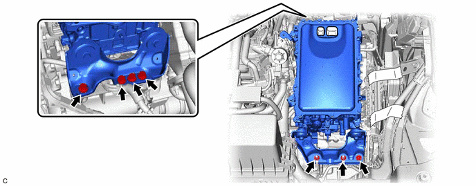
Note
-
When removing the inverter with converter assembly, be careful not to damage the parts around it.
-
To prevent damage, do not hold the inverter with converter assembly by the connectors, brackets or cooling pipes.
-
To prevent damage due to static electricity, do not touch the terminals of the disconnected connectors.
Tech Tips
Even after the coolant is drained, coolant remains in the inverter due to its internal structure. Therefore, seal or cover the pipes when removing the inverter with converter assembly so that coolant does not spill out.
-
-
-
REMOVE NO. 1 INVERTER BRACKET
-
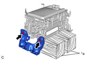
*a Wooden Block Set the inverter with converter assembly on wooden blocks.
Note
Make sure to support the inverter with converter assembly at the positions shown in the illustration, otherwise it may be damaged.
-
Remove the 2 bolts and No. 1 inverter bracket from the inverter with converter assembly.
-
-
REMOVE NO. 2 INVERTER BRACKET
-
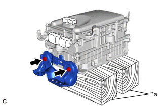
*a Wooden Block Remove the 2 bolts and No. 2 inverter bracket from the inverter with converter assembly.
-
-
REMOVE WIRE HARNESS CLAMP BRACKET (w/o Canister Pump Module)
-
Remove the 2 bolts and 2 wire harness clamp brackets from the inverter with converter assembly.
-
Remove the bolt and wire harness clamp bracket from the inverter with converter assembly.
-
Remove the bolt and wire harness clamp bracket from the inverter with converter assembly.
-
-
REMOVE WIRE HARNESS CLAMP BRACKET (w/ Canister Pump Module)
-
Remove the 2 bolts and 2 wire harness clamp brackets from the inverter with converter assembly.
-
Remove the bolt and wire harness clamp bracket from the inverter with converter assembly.
-
Remove the 2 bolts and wire harness clamp bracket from the inverter with converter assembly.
-