PLUG-IN CHARGE CONTROL SYSTEM ECU Power Source Circuit
DESCRIPTION
The electric vehicle charger assembly is supplied with constant power for operation through the AMD2 terminal. When the power switch is on (IG) or when plug-in charging is being performed, power is supplied to the IGCT terminal via the IGCT SCENE relay. Additionally, the case of the electric vehicle charger assembly acts as the body ground.
WIRING DIAGRAM

CAUTION / NOTICE / HINT
CAUTION:
-

Before the following operations are conducted, take precautions to prevent electric shock by turning the power switch off, wearing insulated gloves, and removing the service plug grip from HV battery.
-
Inspecting the high-voltage system
-
Disconnecting the low voltage connector of the inverter with converter assembly
-
Disconnecting the low voltage connector of the HV battery
-
Disconnecting the low voltage connector of the electric vehicle charger assembly
-
Disconnecting the low voltage connector of the solar energy control unit
-

To prevent electric shock, make sure to remove the service plug grip to cut off the high voltage circuit before servicing the vehicle.
-

After removing the service plug grip from the HV battery, put it in your pocket to prevent other technicians from accidentally reconnecting it while you are working on the high-voltage system.
-

*a Without waiting for 10 minutes After removing the service plug grip, wait for at least 10 minutes before touching any of the high-voltage connectors or terminals. After waiting for 10 minutes, check the voltage at the terminals in the inspection point in the inverter with converter assembly. The voltage should be 0 V before beginning work.
Tech Tips
Waiting for at least 10 minutes is required to discharge the high-voltage capacitor inside the inverter with converter assembly and the electric vehicle charger assembly.
Note
After turning the power switch off, waiting time may be required before disconnecting the cable from the negative (-) auxiliary battery terminal. Therefore, make sure to read the disconnecting the cable from the negative (-) auxiliary battery terminal notices before proceeding with work.
PROCEDURE
-
CHECK DTC OUTPUT (HEALTH CHECK)
-
Connect the GTS to the DLC3.
-
Turn the power switch on (IG).
-
Turn the GTS on.
-
Enter the following menus: Health Check.
-
Check DTCs.
Result Result Proceed to No DTCs are output. A DTCs are output. B -
Turn the power switch off.
B 
GO TO DTC CHART
A 
-
-
CHECK ELECTRIC VEHICLE CHARGER ASSEMBLY (BODY GROUND)
-
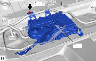
*1 Electric Vehicle Charger Assembly *2 Installation Bolt (for Body Ground) Measure the resistance according to the value(s) in the table below.
Standard Resistance Tester Connection Condition Specified Condition Case of electric vehicle charger assembly - Body ground Always Below 1 Ω Tech Tips
As the electric vehicle charger assembly is grounded through its case, make sure that the ground bolt is tightened to the specified torque.
Result Proceed to OK NG
NG
TIGHTEN INSTALLATION BOLT Click here
OK
-
-
CHECK ELECTRIC VEHICLE CHARGER ASSEMBLY (AMD2 TERMINAL VOLTAGE)
CAUTION:
Be sure to wear insulated gloves.
-
Check that the service plug grip is not installed.
Note
After removing the service plug grip, do not turn the power switch on (READY), unless instructed by the repair manual because this may cause a malfunction.
-
Remove the EV charger duct.
-
Disconnect the N73 solar energy control unit connector. (w/ Solar charging system)
-
Connect the cable to the negative (-) auxiliary battery terminal.
-
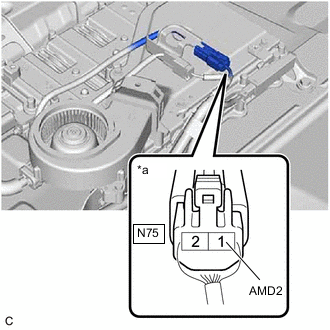
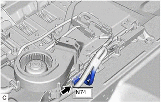
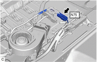
*a Component with harness connected
(Electric Vehicle Charger Assembly)
Measure the voltage according to the value(s) in the table below.
Standard Voltage Tester Connection Condition Specified Condition N75-1 (AMD2) - Body ground Always 11 to 14 V -
Disconnect the cable from the negative (-) auxiliary battery terminal.
-
Reconnect the N73 solar energy control unit connector. (w/ Solar charging system)
-
Install the EV charger duct.
Result Proceed to OK NG
NG 
CHECK FUSE (AMD2) Click here
OK
-
-
CHECK ELECTRIC VEHICLE CHARGER ASSEMBLY (IGCT VOLTAGE)
CAUTION:
Be sure to wear insulated gloves.
-
Check that the service plug grip is not installed.
Note
After removing the service plug grip, do not turn the power switch on (READY), unless instructed by the repair manual because this may cause a malfunction.
-
Remove the EV charger duct.
-
Connect the cable to the negative (-) auxiliary battery terminal.
-
Turn the power switch on (IG).
-
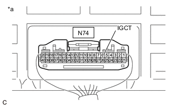
*a Component with harness connected
(Electric Vehicle Charger Assembly)
Measure the voltage according to the value(s) in the table below.
Standard Voltage Tester Connection Condition Specified Condition N74-6 (IGCT) - Body ground Power switch on (IG) 11 to 14 V -
Turn the power switch off.
-
Disconnect the cable from the negative (-) auxiliary battery terminal.
-
Install the EV charger duct.
Result Proceed to OK NG
OK
GO TO PROBLEM SYMPTOMS TABLE (PLUG-IN CHARGE CONTROL SYSTEM) Click here
NG
CHECK FUSE (IGCT NO.4) Click here
-
-
CHECK FUSE (AMD2)
-
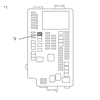
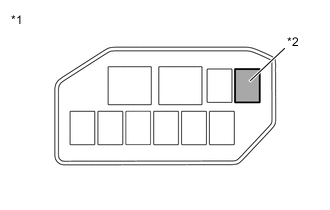
*1 No. 1 Engine Room Relay Block and No. 1 Junction Block Assembly *2 AMD2 Fuse Remove the AMD2 fuse from the No. 1 engine room relay block and No. 1 junction block assembly.
-
Measure the resistance according to the value(s) in the table below.
Standard Resistance Tester Connection Condition Specified Condition AMD2 fuse terminals Always Below 1 Ω -
Install the AMD2 fuse.
Result Proceed to OK NG
OK
REPAIR OR REPLACE HARNESS OR CONNECTOR
NG
CHECK HARNESS AND CONNECTOR (NO. 1 ENGINE ROOM RELAY BLOCK AND NO. 1 JUNCTION BLOCK ASSEMBLY - ELECTRIC VEHICLE CHARGER ASSEMBLY) Click here
-
-
CHECK FUSE (IGCT NO.4)
-
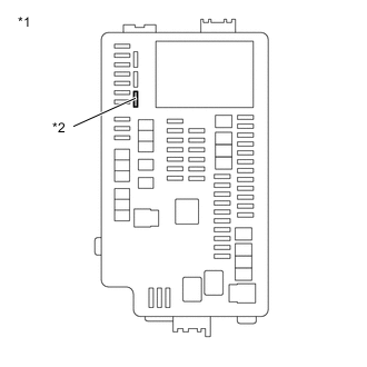
*1 No. 1 Engine Room Relay Block and No. 1 Junction Block Assembly *2 IGCT NO.4 Fuse Remove the IGCT NO. 4 fuse from the No. 1 engine room relay block and No. 1 junction block assembly.
-
Measure the resistance according to the value(s) in the table below.
Standard Resistance Tester Connection Condition Specified Condition IGCT NO. 4 fuse terminals Always Below 1 Ω -
Install the IGCT NO. 4 fuse.
Result Proceed to OK NG
NG
CHECK HARNESS AND CONNECTOR (NO. 1 ENGINE ROOM RELAY BLOCK AND NO. 1 JUNCTION BLOCK ASSEMBLY - ELECTRIC VEHICLE CHARGER ASSEMBLY) Click here
OK
-
-
CHECK HARNESS AND CONNECTOR (NO. 1 ENGINE ROOM RELAY BLOCK AND NO. 1 JUNCTION BLOCK ASSEMBLY - ELECTRIC VEHICLE CHARGER ASSEMBLY)
CAUTION:
Be sure to wear insulated gloves.
-
Check that the service plug grip is not installed.
Note
After removing the service plug grip, do not turn the power switch on (READY), unless instructed by the repair manual because this may cause a malfunction.
-
Remove the IGCT NO.4 fuse from the No. 1 engine room relay block and No. 1 junction block assembly.
-
Remove the EV charger duct.
-
Disconnect the N74 electric vehicle charger assembly connector.
-
Measure the resistance according to the value(s) in the table below.
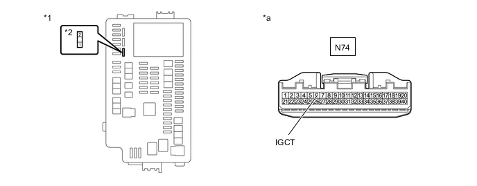
*1 No. 1 Engine Room Relay Block and No. 1 Junction Block Assembly *2 IGCT NO.4 Fuse *a Front view of wire harness connector
(to Electric Vehicle Charger Assembly)
- - Standard Resistance Tester Connection Condition Specified Condition N74-6 (IGCT) - IGCT NO.4 fuse terminal 2 Always Below 1 Ω -
Reconnect the N74 electric vehicle charger assembly connector.
-
Install the EV charger duct.
-
Install the IGCT NO.4 fuse.
Result Proceed to OK NG
NG
REPAIR OR REPLACE HARNESS OR CONNECTOR
OK
-
-
INSPECT RELAY (IGCT SCENE)
-
*1 No. 2 Relay Block Assembly *2 IGCT SCENE Relay Remove the IGCT SCENE relay from the No. 2 relay block assembly.
-
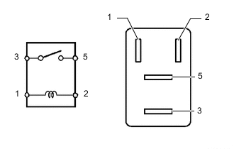
Measure the resistance according to the value(s) in the table below.
Standard Resistance Tester Connection Condition Specified Condition 3 - 5 Auxiliary battery voltage not applied between terminals 1 and 2 10 kΩ or higher Auxiliary battery voltage applied between terminals 1 and 2 Below 1 Ω -
Install the IGCT SCENE relay.
Result Proceed to OK NG
OK
REPAIR OR REPLACE HARNESS OR CONNECTOR
NG
REPLACE RELAY (IGCT SCENE)
-
-
CHECK HARNESS AND CONNECTOR (NO. 1 ENGINE ROOM RELAY BLOCK AND NO. 1 JUNCTION BLOCK ASSEMBLY - ELECTRIC VEHICLE CHARGER ASSEMBLY)
CAUTION:
Be sure to wear insulated gloves.
-
Check that the service plug grip is not installed.
Note
After removing the service plug grip, do not turn the power switch on (READY), unless instructed by the repair manual because this may cause a malfunction.
-
Remove the AMD2 fuse from the No. 1 engine room relay block and No. 1 junction block assembly.
-
Remove the EV charger duct.
-
Disconnect the N75 electric vehicle charger assembly connector.
-
Disconnect the N73 solar energy control unit connector. (w/ Solar charging system)
-
Measure the resistance according to the value(s) in the table below.
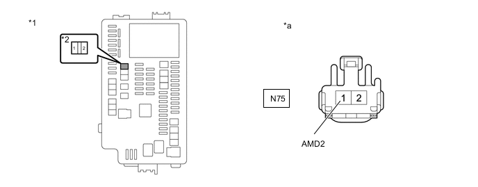
*1 No. 1 Engine Room Relay Block and No. 1 Junction Block Assembly *2 AMD2 Fuse *a Front view of wire harness connector
(to Electric Vehicle Charger Assembly)
- - Standard Resistance Tester Connection Condition Specified Condition N75-1 (AMD2) or AMD2 fuse terminal 2 - Body ground and other terminals Always 10 kΩ or higher -
Reconnect the N73 solar energy control unit connector. (w/ Solar charging system)
-
Reconnect the N75 electric vehicle charger assembly connector.
-
Install the EV charger duct.
-
Install the AMD2 fuse.
Result Proceed to OK NG
OK
REPLACE FUSE (AMD2)
NG
REPAIR OR REPLACE HARNESS OR CONNECTOR Click here
-
-
CHECK HARNESS AND CONNECTOR (NO. 1 ENGINE ROOM RELAY BLOCK AND NO. 1 JUNCTION BLOCK ASSEMBLY - ELECTRIC VEHICLE CHARGER ASSEMBLY)
CAUTION:
Be sure to wear insulated gloves.
-
Check that the service plug grip is not installed.
Note
After removing the service plug grip, do not turn the power switch on (READY), unless instructed by the repair manual because this may cause a malfunction.
-
Remove the IGCT NO.4 fuse from the No. 1 engine room relay block and No. 1 junction block assembly.
-
Remove the EV charger duct.
-
Disconnect the N74 electric vehicle charger assembly connector.
-
Disconnect the N71 solar energy control unit connector. (w/ Solar charging system)
-
Measure the resistance according to the value(s) in the table below.
*1 No. 1 Engine Room Relay Block and No. 1 Junction Block Assembly *2 IGCT NO.4 Fuse *a Front view of wire harness connector
(to Electric Vehicle Charger Assembly)
- - Standard Resistance Tester Connection Condition Specified Condition N74-6 (IGCT) or IGCT NO.4 fuse terminal 2 - Body ground and other terminals Always 10 kΩ or higher -
Reconnect the N71 solar energy control unit connector. (w/ Solar charging system)
-
Reconnect the N74 electric vehicle charger assembly connector.
-
Install the EV charger duct.
-
Install the IGCT NO.4 fuse.
Result Proceed to OK NG
OK
REPLACE FUSE (IGCT NO.4)
NG
REPAIR OR REPLACE HARNESS OR CONNECTOR Click here
-
-
REPAIR OR REPLACE HARNESS OR CONNECTOR
Result Proceed to NEXT
NEXT
REPLACE FUSE (AMD2)
-
REPAIR OR REPLACE HARNESS OR CONNECTOR
Result Proceed to NEXT
NEXT
REPLACE FUSE (IGCT NO.4)