PLUG-IN CHARGE CONTROL SYSTEM Control Pilot Signal Circuit
DESCRIPTION
The electric vehicle charger assembly detects when a charging connector has been connected and charging is possible by using the CPLT signal (control pilot signal). The electric vehicle charger assembly will then start the plug-in charge control system and change the CPLT signal (control pilot signal).
Using the waveform duty ratio of the CPLT signal (control pilot signal), the electric vehicle charger assembly recognizes the rated amperage of a charging facility (a socket using a charging cable) or charging station. By changing the CPLT signal (control pilot signal), the electric vehicle charger assembly transmits the status that the vehicle is ready to start charging, to the charging facility (CCID unit).
WIRING DIAGRAM
Figure 1. for Electric Vehicle Charger Cable Assembly (Type 1)
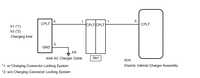
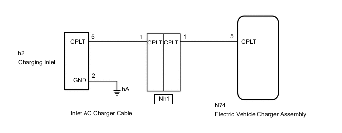
Figure 2. for Electric Vehicle Charger Cable Assembly (Type 2)
CAUTION / NOTICE / HINT
CAUTION:
-

Before the following operations are conducted, take precautions to prevent electric shock by turning the power switch off, wearing insulated gloves, and removing the service plug grip from HV battery.
-
Inspecting the high-voltage system
-
Disconnecting the low voltage connector of the inverter with converter assembly
-
Disconnecting the low voltage connector of the HV battery
-
Disconnecting the low voltage connector of the electric vehicle charger assembly
-
Disconnecting the low voltage connector of the solar energy control unit
-

To prevent electric shock, make sure to remove the service plug grip to cut off the high voltage circuit before servicing the vehicle.
-

After removing the service plug grip from the HV battery, put it in your pocket to prevent other technicians from accidentally reconnecting it while you are working on the high-voltage system.
-

*a Without waiting for 10 minutes After removing the service plug grip, wait for at least 10 minutes before touching any of the high-voltage connectors or terminals. After waiting for 10 minutes, check the voltage at the terminals in the inspection point in the inverter with converter assembly. The voltage should be 0 V before beginning work.
Tech Tips
Waiting for at least 10 minutes is required to discharge the high-voltage capacitor inside the inverter with converter assembly and the electric vehicle charger assembly.
Note
After turning the power switch off, waiting time may be required before disconnecting the cable from the negative (-) auxiliary battery terminal. Therefore, make sure to read the disconnecting the cable from the negative (-) auxiliary battery terminal notices before proceeding with work.
PROCEDURE
-
READ VALUE USING GTS (CHARGING CURRENT DUTY FROM CHARGER, TIME CYCLE OF CHARGING CURRENT DUTY FROM CHARGER)
-
Using the electric vehicle charger cable assembly, plugincharge the vehicle.
-
Connect the GTS to the DLC3.
-
Turn the power switch on (IG).
-
Turn the GTS on.
-
Enter the following menus: Powertrain / Plug-in Control / Data List / Charging Current Duty from Charger, Time Cycle of Charging Current Duty from Charger.
Powertrain > Plug-in Control > Data ListTester Display Charging Current Duty from Charger Time Cycle of Charging Current Duty from Charger -
Read the value displayed on the GTS.
Powertrain > Plug-in Control > Data ListTester Display Measurement Item Normal Condition Charging Current Duty from Charger Duty value of CPLT signal generated from the electric vehicle charger assembly Electric vehicle charger cable assembly connected: 5 to 39%
Not connected to EVSE (charging station) or no power supplied: 0%
Time Cycle of Charging Current Duty from Charger Duration of 1 cycle of CPLT signal CPLT (control pilot signal) generated: 951 to 1049 μs -
Turn the power switch off.
-
Disconnect the electric vehicle charger cable assembly.
Result Result Proceed to Values are as specified in Normal Condition column A Values are not as specified in Normal Condition column B -
A 
GO TO PROBLEM SYMPTOMS TABLE (PLUG-IN CHARGE CONTROL SYSTEM) Click here
B 
-
-
CHECK INLET AC CHARGER CABLE (BODY GROUND)
-
Open the charging port lid.
-
for Electric vehicle charger cable assembly (Type 1):
-
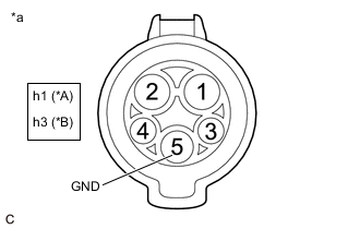
*A w/ Charging Connector Locking System *B w/o Charging Connector Locking System *a Inlet AC Charger Cable (for Type 1)
(Charging Inlet Side)
Measure the resistance according to the value(s) in the table below.
Standard Resistance w/ Charging Connector Locking System Tester Connection Condition Specified Condition h1-5 (GND) - Body ground Power switch off Below 1 Ω w/o Charging Connector Locking System Tester Connection Condition Specified Condition h3-5 (GND) - Body ground Power switch off Below 1 Ω
-
-
for Electric vehicle charger cable assembly (Type 2):
-
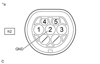
*a Inlet AC Charger Cable (for Type 2)
(Charging Inlet Side)
Measure the resistance according to the value(s) in the table below.
Standard Resistance Tester Connection Condition Specified Condition h2-2 (GND) - Body ground Power switch off Below 1 Ω
-
-
Close the charging port lid.
Result Proceed to OK NG
NG 
CHECK INLET AC CHARGER CABLE (BODY GROUND TERMINAL CONNECTION CONDITION) Click here
OK
-
-
CHECK HARNESS AND CONNECTOR (ELECTRIC VEHICLE CHARGER ASSEMBLY - CHARGING INLET)
CAUTION:
Be sure to wear insulated gloves.
-
Check that the service plug grip is not installed.
Note
After removing the service plug grip, do not turn the power switch on (READY), unless instructed by the repair manual because this may cause a malfunction.
-
Open the charging port lid.
-
Remove the EV charger duct.
-
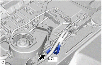
Disconnect the N74 electric vehicle charger assembly connector.
-
for Electric vehicle charger cable assembly (Type 1):
-
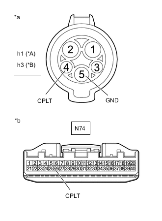
*A w/ Charging Connector Locking System *B w/o Charging Connector Locking System *a Inlet AC Charger Cable (for Type 1)
(Charging Inlet Side)
*b Front view of wire harness connector
(to Electric Vehicle Charger Assembly)
Measure the resistance according to the value(s) in the table below.
Standard Resistance w/ Charging Connector Locking System Tester Connection Condition Specified Condition h1-4 (CPLT) - N74-5 (CPLT) Power switch off Below 1 Ω h1-4(CPLT) or N74-5(CPLT) - Body ground and other terminals Power switch off 10 kΩ or higher h1-5 (GND) - Other terminals Power switch off 10 kΩ or higher w/o Charging Connector Locking System Tester Connection Condition Specified Condition h3-4 (CPLT) - N74-5 (CPLT) Power switch off Below 1 Ω h3-4(CPLT) or N74-5(CPLT) - Body ground and other terminals Power switch off 10 kΩ or higher h3-5 (GND) - Other terminals Power switch off 10 kΩ or higher -
Connect the cable to the negative (-) auxiliary battery terminal.
-
Turn the power switch on (IG).
-
Measure the voltage according to the value(s) in the table below.
Standard Voltage w/ Charging Connector Locking System Tester Connection Condition Specified Condition h1-4 (CPLT) or N74-5 (CPLT) - Body ground Power switch on (IG) Below 1 V w/o Charging Connector Locking System Tester Connection Condition Specified Condition h3-4 (CPLT) or N74-5 (CPLT) - Body ground Power switch on (IG) Below 1 V Note
Turning the power switch on (IG) with the electric vehicle charger assembly connector disconnected causes other DTCs to be stored. Clear the DTCs after performingthis inspection.
-
-
for Electric vehicle charger cable assembly (Type 2):
-
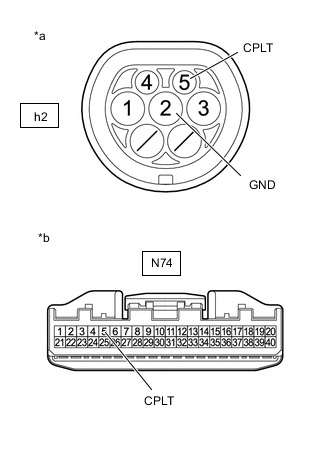
*a Inlet AC Charger Cable (for Type 2)
(Charging Inlet Side)
*b Front view of wire harness connector
(to Electric Vehicle Charger Assembly)
Measure the resistance according to the value(s) in the table below.
Standard Resistance Tester Connection Condition Specified Condition h2-5 (CPLT) - N74-5 (CPLT) Power switch off Below 1 Ω h2-5(CPLT) or N74-5(CPLT) - Body ground and other terminals Power switch off 10 kΩ or higher h2-2 (GND) - Other terminals Power switch off 10 kΩ or higher -
Connect the cable to the negative (-) auxiliary battery terminal.
-
Turn the power switch on (IG).
-
Measure the voltage according to the value(s) in the table below.
Standard Voltage Tester Connection Condition Specified Condition h2-5 (CPLT) or N74-5 (CPLT) - Body ground Power switch on (IG) Below 1 V Note
Turning the power switch on (IG) with the electric vehicle charger assembly connector disconnected causes other DTCs to be stored. Clear the DTCs after performingthis inspection.
-
-
Turn the power switch off.
-
Disconnect the cable from the negative (-) auxiliary battery terminal.
-
Reconnect the N74 electric vehicle charger assembly connector.
-
Install the EV charger duct.
-
Close the charging port lid.
Result Proceed to OK NG
NG
CHECK HARNESS AND CONNECTOR (ELECTRIC VEHICLE CHARGER ASSEMBLY - INLET AC CHARGER CABLE) Click here
OK
-
-
INSPECT ELECTRIC VEHICLE CHARGER CABLE ASSEMBLY (CPLT TERMINAL VOLTAGE)
Result Proceed to OK NG
OK
REPLACE ELECTRIC VEHICLE CHARGER ASSEMBLY Click here
NG
REPLACE ELECTRIC VEHICLE CHARGER CABLE ASSEMBLY
-
CHECK INLET AC CHARGER CABLE (BODY GROUND TERMINAL CONNECTION CONDITION)
-
Check the installation condition of the ground wire hA.
OK The ground wire is securely installed. Result Proceed to OK NG
OK
REPLACE INLET AC CHARGER CABLE Click here
NG
CONNECT SECURELY
-
-
CHECK HARNESS AND CONNECTOR (ELECTRIC VEHICLE CHARGER ASSEMBLY - INLET AC CHARGER CABLE)
CAUTION:
Be sure to wear insulated gloves.
-
Check that the service plug grip is not installed.
Note
After removing the service plug grip, do not turn the power switch on (READY), unless instructed by the repair manual because this may cause a malfunction.
-
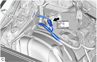
*1 Nh1 Disconnect the Nh1 inlet AC charger cable connector.
Note
If the Nh1 connector is disconnected with the auxiliary battery connected, P0D5615 may be detected. Check that the cable is disconnected from the negative (-) auxiliary battery terminal before proceeding work. (for Electric vehicle charger cable assembly (Type 1))
-
Remove the EV charger duct.
-
Disconnect the N74 electric vehicle charger assembly connector.
-
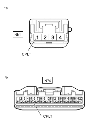
*a Front view of wire harness connector
(to Inlet AC Charger Cable)
*b Front view of wire harness connector
(to Electric Vehicle Charger Assembly)
Measure the resistance according to the value(s) in the table below.
Standard Resistance Tester Connection Condition Specified Condition Nh1-1 (CPLT) - N74-5 (CPLT) Power switch off Below 1 Ω Nh1-1 (CPLT) or N74-5 (CPLT) - Body ground and other terminals Power switch off 10 kΩ or higher -
Connect the cable to the negative (-) auxiliary battery terminal.
-
Turn the power switch on (IG).
-
Measure the voltage according to the value(s) in the table below.
Standard Voltage Tester Connection Condition Specified Condition Nh1-1 (CPLT) or N74-5 (CPLT) - Body ground Power switch on (IG) Below 1 V Note
Turning the power switch on (IG) with the electric vehicle charger assembly connector disconnected causes DTCs to be stored. Clear the DTCs after performing this inspection.
-
Turn the power switch off.
-
Disconnect the cable from the negative (-) auxiliary battery terminal.
-
Reconnect the N74 electric vehicle charger assembly connector.
-
Install the EV charger duct.
-
Reconnect the Nh1 inlet AC charger cable connector.
Result Proceed to OK NG
OK
REPLACE INLET AC CHARGER CABLE Click here
NG
REPAIR OR REPLACE HARNESS OR CONNECTOR
-