PLUG-IN CHARGE CONTROL SYSTEM Cannot Lock Charging Connector
DESCRIPTION
If the lock and unlock functions of the charging connector lock do not operate, the electric vehicle charger assembly, smart key ECU assembly (certification ECU), charging connector lock motor (cable EV charger lock assembly), charging connector lock/unlock switch (EV charger lid switch assembly) or electrical key transmitter sub-assembly may be malfunctioning or the vehicle may be being affected by wave interference.
CAUTION / NOTICE / HINT
CAUTION:
-

Before the following operations are conducted, take precautions to prevent electric shock by turning the power switch off, wearing insulated gloves, and removing the service plug grip from HV battery.
-
Inspecting the high-voltage system
-
Disconnecting the low voltage connector of the inverter with converter assembly
-
Disconnecting the low voltage connector of the HV battery
-
Disconnecting the low voltage connector of the electric vehicle charger assembly
-
Disconnecting the low voltage connector of the solar energy control unit
-

To prevent electric shock, make sure to remove the service plug grip to cut off the high voltage circuit before servicing the vehicle.
-

After removing the service plug grip from the HV battery, put it in your pocket to prevent other technicians from accidentally reconnecting it while you are working on the high-voltage system.
-

*a Without waiting for 10 minutes After removing the service plug grip, wait for at least 10 minutes before touching any of the high-voltage connectors or terminals. After waiting for 10 minutes, check the voltage at the terminals in the inspection point in the inverter with converter assembly. The voltage should be 0 V before beginning work.
Tech Tips
Waiting for at least 10 minutes is required to discharge the high-voltage capacitor inside the inverter with converter assembly and the electric vehicle charger assembly.
Note
-
After turning the power switch off, waiting time may be required before disconnecting the cable from the negative (-) auxiliary battery terminal. Therefore, make sure to read the disconnecting the cable from the negative (-) auxiliary battery terminal notices before proceeding with work.
-
The charging connector locking system uses the entry and start system (for Entry Function). If the entry function is malfunctioning, the lock functions of the charging port lid and charging connector may not operate. (for Electric vehicle charger cable assembly (Type 1))
If the entry function is malfunctioning, inspect the entry and start system (for Entry Function) first.
-
Make sure that the entry and start system (for Entry Function) is not canceled through a customize setting before performing this troubleshooting procedure. (for Electric vehicle charger cable assembly (Type 1))
-
To protect the charging port lid lock motor and charging connector lock motor, if the charging port lid lock or charging connector lock is operated repeatedly, operation of the lock will be prohibited. Wait for 3 minutes or more to allow the motor to cool and then resume the inspection.
-
To protect the charging port lid lock motor and charging connector lock motor, if the charging port lid lock and charging connector lock are operated repeatedly in quick succession, operation of the lock will be prohibited for a certain amount of time. Wait for 3 seconds or more after operation was prohibited and then resume the inspection.
-
If the charging connector lock is dirty or frozen, or if foreign matter is caught between the charging connector and charging connector lock, the charging connector may not be able to be locked/unlocked. Clean the charging connector lock before performing the inspection.
-
If a charging cable other than the charging cable provided with the vehicle is used, the charging connector lock may not operate correctly. Check that the lock and unlock functions of the charging connector lock operate properly using the charging cable provided with the vehicle before proceeding with the inspection.
-
When the charging connector is connected, changing the "Charging Connector Lock" customize setting (to "Auto Lock" or "Auto Lock & Auto Unlock") will not lock or unlock the charging connector. (for Electric vehicle charger cable assembly (Type 1))
-
The charging connector lock may not operate if the charging port lid lock emergency release lever has been operated. In this case, extend the push lifter of the EV charger lid switch assembly (charging lid courtesy switch) and then connect the charging connector to operate the charging connector lock.
-
The charging connector lock may not operate if the charging connector lock emergency release lever has been operated. In this case, disconnect the charging connector and push in the push lifter of the EV charger lid switch assembly (charging lid courtesy switch)). (for Electric vehicle charger cable assembly (Type 1))
-
The charging connector lock may not operate if the charging connector lock emergency release lever has been operated. In this case, disconnect and then connect the charging connector to operate the charging connector lock. (for Electric vehicle charger cable assembly (Type 2))
-
Make sure that the plug-in charge control system customize setting "Charging Connector Lock" is set to "Manual Lock" before performing the following procedure. (for Electric vehicle charger cable assembly (Type 1))
PROCEDURE
-
CHECK DTC OUTPUT (HEALTH CHECK)
-
Connect the GTS to the DLC3.
-
Turn the power switch on (IG).
-
Enter the following menus: Health Check.
-
Check DTCs.
Result Result Proceed to No DTCs output
(for Electric vehicle charger cable assembly (Type 1))
A No DTCs output
(for Electric vehicle charger cable assembly (Type 2))
B DTCs output C -
Turn the power switch off.
B 
CHECK ELECTRIC VEHICLE CHARGER ASSEMBLY (CHARGING PORT LID OPEN AND CHARGING CONNECTOR LOCK UNLOCKED) Click here
C 
GO TO DTC CHART
A 
-
-
CHECK ENTRY AND START SYSTEM (FOR ENTRY FUNCTION) OPERATION
Tech Tips
Make sure to perform this inspection with all of the doors locked. (The entry function and charging port lid verification function cannot be operated if any of the doors are unlocked.)
Result Result Proceed to Entry function operates (doors can be locked/unlocked using entry function) A Entry function does not operate (doors cannot be locked/unlocked using entry function) B
B
GO TO ENTRY AND START SYSTEM (FOR ENTRY FUNCTION) Click here
A
-
CHECK ENTRY AND START SYSTEM OPERATION (FOR CHARGING PORT LID)
-
Close all of the doors.
-
Lock all of the doors.
-
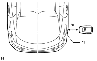
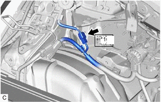
*1 Charging Port Lid *a 0.7 to 1 m (2.30 to 3.28 ft.) Hold the electrical key transmitter sub-assembly at the same height as the charging port lid and approximately 0.7 to 1 m (2.30 to 3.28 ft.) from the vehicle as shown in the illustration and check that the LED of the electrical key transmitter sub-assembly blinks.
Tech Tips
-
The charging port lid is located on the rear right side of the vehicle.
-
Make sure to perform this inspection with all of the doors locked. (The entry function and charging port lid verification function cannot be operated if any of the doors are unlocked.)
-
-
*1 No. 2 Electrical Key Antenna (Extra Antenna) *a Approximately 0.3 m (0.983 ft.) Hold the electrical key transmitter sub-assembly at the same height as the No. 2 electrical key antenna (extra antenna) and approximately 0.3 m (0.983 ft.) from the vehicle as shown in the illustration and check that the LED of the electrical key transmitter sub-assembly blinks.
Tech Tips
-
The No. 2 electrical key antenna (extra antenna) is located on the rear right side of the vehicle under the charging port lid.
-
When the electrical key transmitter sub-assembly is brought near the No. 2 electrical key antenna (extra antenna), the possibility of wave interference decreases, and it can be determined if wave interference is causing the problem symptom.
-
If the inspection result is that the problem only occurs in certain locations or at certain times of day, the possibility of wave interference is high. Also, added vehicle components may cause wave interference. If installed, remove them and perform the operation check.
-
There may be wave interference if the vehicle is near broadcasting antennas, large video displays, wireless garage door opener systems, wireless security cameras, home security systems, etc. In this case, move the vehicle to a different location and check if there is any improvement.
-
Communication may not be possible if the electrical key transmitter sub-assembly is within 0.2 m (0.656 ft.) of the charging port lid.
Result Result Proceed to LED of electrical key transmitter sub-assembly does not blink
(charging port lid verification function does not operate)
A When electrical key transmitter sub-assembly brought near charging port lid, LED blinks
(charging port lid verification function operates)
B When electrical key transmitter sub-assembly brought near charging port lid, LED does not blink, but when brought near No. 2 electrical key antenna (extra antenna), LED blinks.
(charging port lid verification function operates)
C -
A
GO TO ENTRY AND START SYSTEM (FOR ENTRY FUNCTION) (CHARGING CONNECTOR ENTRY LOCK FUNCTION DOES NOT OPERATE) Click here
C
AFFECTED BY WAVE INTERFERENCE
B
-
-
CHECK ELECTRIC VEHICLE CHARGER ASSEMBLY (CHARGING PORT LID OPEN AND CHARGING CONNECTOR LOCK UNLOCKED)
CAUTION:
Be sure to wear insulated gloves.
-
Check that the service plug grip is not installed.
Note
After removing the service plug grip, do not turn the power switch on (READY), unless instructed by the repair manual because this may cause a malfunction.
-
Remove the EV charger duct.
-
Connect the cable to the negative (-) auxiliary battery terminal.
-
Lock all of the doors.
-
While carrying the electrical key transmitter sub-assembly, open the charging port lid.
-
Turn the power switch on (IG).
-
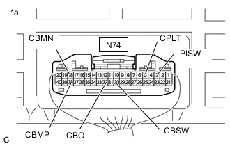
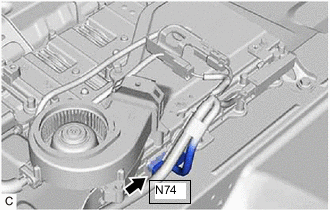
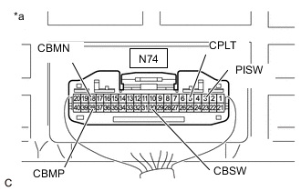
*a Component with harness connected
(Electric Vehicle Charger Assembly)
Measure the voltage according to the value(s) in the table below.
Tech Tips
Opening the charging port lid with all of the doors locked will unlock the charging connector lock.
Measure the voltage with the charging connector lock unlocked.
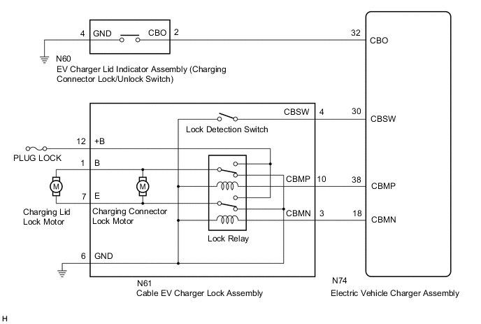
Standard Voltage Tester Connection Condition Specified Condition N74-30 (CBSW) - Body ground Power switch on (IG) 4.5 to 5.5 V N74-38 (CBMP) - Body ground Power switch on (IG) 0 to 1.5 V N74-18 (CBMN) - Body ground Power switch on (IG) 0 to 1.5 V N74-32 (CBO) - Body ground Power switch on (IG) 11 to 14 V N74-3 (PISW) - Body ground Power switch on (IG) 3.572 to 4.730 V N74-5 (CPLT) - Body ground Power switch on (IG) 0 to 1.5 V -
Connect the GTS to the DLC3.
-
Turn the GTS on.
-
Enter the following menus: Powertrain / Plug-in Control / Data List / Charging Connector Connect Status Voltage, Charging Connector Lock Switch Status, Charging Connector Lock Pin Status, Charging Connector Lock Motor Unlock Direction Revolution Request Current, Charging Connector Lock Motor Lock Direction Revolution Request Current, Charging Current Duty from Charger, Time Cycle of Charging Current Duty from Charger.
Powertrain > Plug-in Control > Data ListTester Display Charging Connector Connect Status Voltage Charging Connector Lock Switch Status Charging Connector Lock Pin Status Charging Connector Lock Motor Unlock Direction Revolution Request Current Charging Connector Lock Motor Lock Direction Revolution Request Current Charging Current Duty from Charger Time Cycle of Charging Current Duty from Charger -
Read the value displayed on the GTS.
Powertrain > Plug-in Control > Data ListTester Display Measurement Item Normal Condition Charging Connector Connect Status Voltage PISW terminal voltage used for checking electric vehicle charger cable assembly connection condition
(PISW)
Electric vehicle charger cable assembly (for type 1) not connected: 3.572 to 4.730 V Charging Connector Lock Switch Status Charging connector lock/unlock switch (EV charger lid indicator assembly) status
(CBO)
Charging connector lock/unlock switch (EV charger lid indicator assembly) not operated: OFF Charging Connector Lock Pin Status Charging connector lock pin status
(CBSW)
Charging connector lock pin not extended: Unlock Charging Connector Lock Motor Unlock Direction Revolution Request Current Output of current to operate charging connector lock motor in reverse
(CBMN)
Charging connector lock motor not operated: OFF Charging Connector Lock Motor Lock Direction Revolution Request Current Output of current to operate charging connector lock motor forward
(CBMP)
Charging connector lock motor not operated: OFF Charging Current Duty from Charger Duty value of CPLT signal generated from the electric vehicle charger assembly
(CPLT)
Electric vehicle charger cable assembly (for type 1) not connected: 0% Time Cycle of Charging Current Duty from Charger Duration of 1 cycle of CPLT signal
(CPLT)
Electric vehicle charger cable assembly (for type 1) not connected: 0 μs Tech Tips
The state of each terminal can be checked on the Data List.
-
Turn the power switch off.
-
Close the charging port lid.
-
Disconnect the cable from the negative (-) auxiliary battery terminal.
-
Install the EV charger duct.
Result Result Proceed to OK A NG
(CBSW)
B NG
(CBMP, CBMN)
C NG
(CBO)
D NG
(PISW)
E NG
(CPLT)
F
B
GO TO STEP 7 Click here
C
GO TO STEP 10 Click here
D
GO TO STEP 13 Click here
E
GO TO STEP 16 Click here
F
GO TO STEP 19 Click here
A
-
-
CHECK ELECTRIC VEHICLE CHARGER ASSEMBLY (CHARGING PORT LID OPEN AND CHARGING CONNECTOR LOCK LOCKED)
CAUTION:
Be sure to wear insulated gloves.
Tech Tips
Make sure that the hybrid control system customize setting "Charging Connector Lock" is set to "Manual Lock" before performing the following procedure.
-
Check that the service plug grip is not installed.
Note
After removing the service plug grip, do not turn the power switch on (READY), unless instructed by the repair manual because this may cause a malfunction.
-
Remove the EV charger duct.
-
Connect the cable to the negative (-) auxiliary battery terminal.
-
Unlock all of the doors.
-
While carrying the electrical key transmitter sub-assembly, open the charging port lid.
-
Check that the charging connector lock is unlocked (lock pin is not extended).
Tech Tips
If the charging connector lock is locked (the lock pin is extended), unlock it using the charging connector lock emergency release lever.
-
Connect the electric vehicle charger cable assembly.
Tech Tips
Make sure that the charging connector is connected securely. If the charging connector is not connected securely, the charging connector lock may not operate properly.
-
Press the charging connector lock/unlock switch (EV charger lid indicator assembly) once to lock the charging connector lock.
-
Turn the power switch on (IG).
-
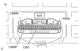
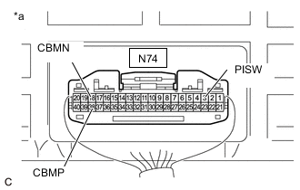
*a Component with harness connected
(Electric Vehicle Charger Assembly)
Measure the voltage according to the value(s) in the table below.
Tech Tips
Pressing the charging connector lock/unlock switch (EV charger lid indicator assembly) once with the charging port lid open and the charging connector connected will lock the charging connector lock. Measure the voltage with the charging connector lock locked.
Standard Voltage Tester Connection Condition Specified Condition N74-38 (CBMP) - Body ground Power switch on (IG) 0 to 1.5 V N74-18 (CBMN) - Body ground Power switch on (IG) 0 to 1.5 V N74-32 (CBO) - Body ground Power switch on (IG) 11 to 14 V N74-3 (PISW) - Body ground Power switch on (IG) 0.350 to 3.572 V -
Connect the GTS to the DLC3.
-
Turn the GTS on.
-
Enter the following menus: Powertrain / Plug-in Control / Data List / Charging Connector Connect Status Voltage, Charging Connector Lock Switch Status, Charging Connector Lock Pin Status, Charging Connector Lock Motor Unlock Direction Revolution Request Current, Charging Connector Lock Motor Lock Direction Revolution Request Current, Charging Current Duty from Charger, Time Cycle of Charging Current Duty from Charger.
Powertrain > Plug-in Control > Data ListTester Display Charging Connector Connect Status Voltage Charging Connector Lock Switch Status Charging Connector Lock Pin Status Charging Connector Lock Motor Unlock Direction Revolution Request Current Charging Connector Lock Motor Lock Direction Revolution Request Current Charging Current Duty from Charger Time Cycle of Charging Current Duty from Charger -
Read the value displayed on the GTS.
Powertrain > Plug-in Control > Data ListTester Display Measurement Item Normal Condition Charging Connector Connect Status Voltage PISW terminal voltage used for checking electric vehicle charger cable assembly connection condition
(PISW)
Electric vehicle charger cable assembly (for type 1) connected: 0.350 to 3.572 V Charging Connector Lock Switch Status Charging connector lock/unlock switch (EV charger lid indicator assembly) status
(CBO)
Charging connector lock/unlock switch (EV charger lid indicator assembly) not operated: OFF Charging Connector Lock Pin Status Charging connector lock pin status
(CBSW)
Charging connector lock pin extended: Lock Charging Connector Lock Motor Unlock Direction Revolution Request Current Output of current to operate charging connector lock motor in reverse
(CBMN)
Charging connector lock motor not operated: OFF Charging Connector Lock Motor Lock Direction Revolution Request Current Output of current to operate charging connector lock motor forward
(CBMP)
Charging connector lock motor not operated: OFF Charging Current Duty from Charger Duty value of CPLT signal generated from the electric vehicle charger assembly
(CPLT)
Electric vehicle charger cable assembly (for type 1) connected: 5 to 39% Time Cycle of Charging Current Duty from Charger Duration of 1 cycle of CPLT signal
(CPLT)
CPLT (control pilot signal) generated: 951 to 1049 μs Tech Tips
The state of each terminal can be checked on the Data List.
-
Turn the power switch off.
-
Press the charging connector lock/unlock switch (EV charger lid indicator assembly) once to unlock the charging connector lock.
-
Disconnect the electric vehicle charger cable assembly.
-
Close the charging port lid.
-
Disconnect the cable from the negative (-) auxiliary battery terminal.
-
Install the EV charger duct.
Result Result Proceed to OK A NG
(CBSW)
B NG
(CBMP, CBMN)
C NG
(CBO)
D NG
(PISW)
E NG
(CPLT)
F
B
CHECK ELECTRIC VEHICLE CHARGER ASSEMBLY (CBSW TERMINAL VOLTAGE) Click here
C
CHECK ELECTRIC VEHICLE CHARGER ASSEMBLY (CBMP, CBMN TERMINAL VOLTAGE) Click here
D
CHECK ELECTRIC VEHICLE CHARGER ASSEMBLY (CBO TERMINAL VOLTAGE) Click here
E
CHECK ELECTRIC VEHICLE CHARGER ASSEMBLY (PISW TERMINAL VOLTAGE) Click here
F
CHECK ELECTRIC VEHICLE CHARGER ASSEMBLY (CPLT TERMINAL VOLTAGE) Click here
A
-
-
INSPECT CABLE EV CHARGER LOCK ASSEMBLY (FOR ELECTRIC VEHICLE CHARGER CABLE ASSEMBLY (TYPE 1))
Result Proceed to OK NG
OK
CAUSE ANALYSIS (ENVIRONMENT/USER RELATED CAUSE) Perform cause analysis in the order of "Environment" and "User" categories as specified in the following tables. Explain to the customer that, due to the temperature of the charging connector lock motor becoming high, to protect the charging connector lock motor, charging connector lock operation was prohibited. Wait 3 minutes or more after lock/unlock operation is prohibited, then resume inspection. Explain to the customer that as the entry function was disabled, the charging connector lock did not operate. Operating the charging connector lock when the entry function is disabled: If customize setting set to "Manual Lock": With all of the doors unlocked, connect the charging connector and press the charging connector lock/unlock switch (EV charger lid indicator assembly). If customize setting set to "Auto Lock" or "Auto Lock & Auto Unlock": Connect the charging connector. Explain to the customer that the charging connector lock may not operate if the charging port lid lock emergency release lever has been operated. Connect the charging connector with the push lifter of the EV charger lid switch assembly (charging lid courtesy switch) extended. Explain to the customer that the charging connector lock may not operate if the charging connector lock emergency release lever has been operated. Disconnect and then connect the charging connector. Explain to the customer that charging connector lock/unlock operation may be prohibited after the auxiliary battery has been replaced or the cable has been disconnected and reconnected to the negative (-) auxiliary battery terminal. Operate the charging connector lock/unlock again. Take appropriate action in accordance with the result of the cause analysis.
NG
REPLACE CABLE EV CHARGER LOCK ASSEMBLY Click here
-
CHECK ELECTRIC VEHICLE CHARGER ASSEMBLY (CBSW TERMINAL VOLTAGE)
CAUTION:
Be sure to wear insulated gloves.
-
Check that the service plug grip is not installed.
Note
After removing the service plug grip, do not turn the power switch on (READY), unless instructed by the repair manual because this may cause a malfunction.
-
Remove the EV charger duct.
-
Disconnect the N74 electric vehicle charger assembly connector.
-
Connect the cable to the negative (-) auxiliary battery terminal.
-
Turn the power switch on (IG).
-
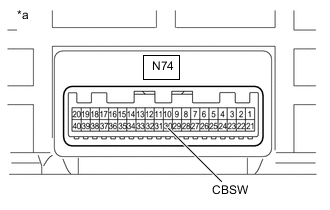
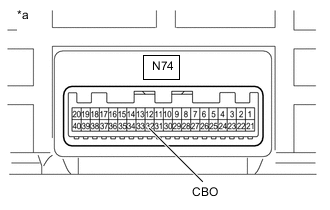
*a Component without harness connected
(Electric Vehicle Charger Assembly)
Measure the voltage according to the value(s) in the table below.
Standard Voltage Tester Connection Condition Specified Condition N74-30 (CBSW) - Body ground Power switch on (IG) 4.5 to 5.5 V -
Turn the power switch off.
-
Disconnect the cable from the negative (-) auxiliary battery terminal.
-
Reconnect the N74 electric vehicle charger assembly connector.
-
Install the EV charger duct.
Result Proceed to OK NG
NG
REPLACE ELECTRIC VEHICLE CHARGER ASSEMBLY Click here
OK
-
-
INSPECT CABLE EV CHARGER LOCK ASSEMBLY (CHARGING CONNECTOR LOCK DETECTION SWITCH) (FOR ELECTRIC VEHICLE CHARGER CABLE ASSEMBLY (TYPE 1))
Result Proceed to OK NG
NG
REPLACE CABLE EV CHARGER LOCK ASSEMBLY Click here
OK
-
CHECK HARNESS AND CONNECTOR (ELECTRIC VEHICLE CHARGER ASSEMBLY - CABLE EV CHARGER LOCK ASSEMBLY (CBSW))
CAUTION:
Be sure to wear insulated gloves.
-
Check that the service plug grip is not installed.
Note
After removing the service plug grip, do not turn the power switch on (READY), unless instructed by the repair manual because this may cause a malfunction.
-
Remove the EV charger duct.
-
Disconnect the N74 electric vehicle charger assembly connector.
-
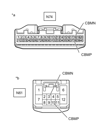
Disconnect the N61 cable EV charger lock assembly connector.
-
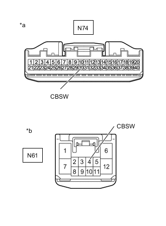
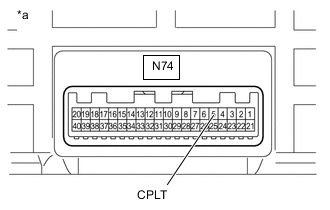
*a Front view of wire harness connector
(to Electric Vehicle Charger Assembly)
*b Front view of wire harness connector
(to Cable EV Charger Lock Assembly)
Measure the resistance according to the value(s) in the table below.
Standard Resistance Tester Connection Condition Specified Condition N74-30 (CBSW) - N61-4 (CBSW) Power switch off Below 1 Ω N74-30 (CBSW) or N61-4 (CBSW) - Body ground and other terminals Power switch off 10 kΩ or higher -
Reconnect the N61 cable EV charger lock assembly connector.
-
Reconnect the N74 electric vehicle charger assembly connector.
-
Install the EV charger duct.
Result Proceed to OK NG
OK
CAUSE ANALYSIS (ENVIRONMENT/USER RELATED CAUSE) Perform cause analysis in the order of "Environment" and "User" categories as specified in the following tables. Explain to the customer that, due to the temperature of the charging connector lock motor becoming high, to protect the charging connector lock motor, charging connector lock operation was prohibited. Wait 3 minutes or more after lock/unlock operation is prohibited, then resume inspection. Explain to the customer that as the entry function was disabled, the charging connector lock did not operate. Operating the charging connector lock when the entry function is disabled: If customize setting set to "Manual Lock": With all of the doors unlocked, connect the charging connector and press the charging connector lock/unlock switch (EV charger lid indicator assembly). If customize setting set to "Auto Lock" or "Auto Lock & Auto Unlock": Connect the charging connector. Explain to the customer that the charging connector lock may not operate if the charging port lid lock emergency release lever has been operated. Connect the charging connector with the push lifter of the EV charger lid switch assembly (charging lid courtesy switch) extended. Explain to the customer that the charging connector lock may not operate if the charging connector lock emergency release lever has been operated. Disconnect and then connect the charging connector. Explain to the customer that charging connector lock/unlock operation may be prohibited after the auxiliary battery has been replaced or the cable has been disconnected and reconnected to the negative (-) auxiliary battery terminal. Operate the charging connector lock/unlock again. Take appropriate action in accordance with the result of the cause analysis.
NG
REPAIR OR REPLACE HARNESS OR CONNECTOR
-
-
CHECK ELECTRIC VEHICLE CHARGER ASSEMBLY (CBMP, CBMN TERMINAL VOLTAGE)
CAUTION:
Be sure to wear insulated gloves.
-
Check that the service plug grip is not installed.
Note
After removing the service plug grip, do not turn the power switch on (READY), unless instructed by the repair manual because this may cause a malfunction.
-
Remove the EV charger duct.
-
Disconnect the N74 electric vehicle charger assembly connector.
-
Connect the cable to the negative (-) auxiliary battery terminal.
-
Turn the power switch on (IG).
-
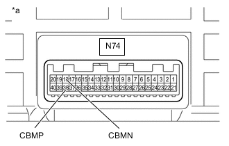
*a Component without harness connected
(Electric Vehicle Charger Assembly)
Measure the voltage according to the value(s) in the table below.
Standard Voltage Tester Connection Condition Specified Condition N74-38 (CBMP) - Body ground Power switch on (IG) 0 to 1.5 V N74-18 (CBMN) - Body ground Power switch on (IG) 0 to 1.5 V -
Turn the power switch off.
-
Disconnect the cable from the negative (-) auxiliary battery terminal.
-
Reconnect the N74 electric vehicle charger assembly connector.
-
Install the EV charger duct.
Result Proceed to OK NG
NG
REPLACE ELECTRIC VEHICLE CHARGER ASSEMBLY Click here
OK
-
-
INSPECT CABLE EV CHARGER LOCK ASSEMBLY (CHARGING CONNECTOR LOCK RELAY) (FOR ELECTRIC VEHICLE CHARGER CABLE ASSEMBLY (TYPE 1))
Result Proceed to OK NG
NG
REPLACE CABLE EV CHARGER LOCK ASSEMBLY Click here
OK
-
CHECK HARNESS AND CONNECTOR (ELECTRIC VEHICLE CHARGER ASSEMBLY - CABLE EV CHARGER LOCK ASSEMBLY (CBMP, CBMN))
CAUTION:
Be sure to wear insulated gloves.
-
Check that the service plug grip is not installed.
Note
After removing the service plug grip, do not turn the power switch on (READY), unless instructed by the repair manual because this may cause a malfunction.
-
Remove the EV charger duct.
-
Disconnect the N74 electric vehicle charger assembly connector.
-
Disconnect the N61 cable EV charger lock assembly connector.
-
*a Front view of wire harness connector
(to Electric Vehicle Charger Assembly)
*b Front view of wire harness connector
(to Cable EV Charger Lock Assembly)
Measure the resistance according to the value(s) in the table below.
Standard Resistance Tester Connection Condition Specified Condition N74-38 (CBMP) - N61-10 (CBMP) Power switch off Below 1 Ω N74-38 (CBMP) or N61-10 (CBMP) - Body ground and other terminals Power switch off 10 kΩ or higher N74-18 (CBMN) - N61-3 (CBMN) Power switch off Below 1 Ω N74-18 (CBMN) or N61-3 (CBMN) - Body ground and other terminals Power switch off 10 kΩ or higher -
Reconnect the N61 cable EV charger lock assembly connector.
-
Reconnect the N74 electric vehicle charger assembly connector.
-
Install the EV charger duct.
Result Proceed to OK NG
OK
CAUSE ANALYSIS (ENVIRONMENT/USER RELATED CAUSE) Perform cause analysis in the order of "Environment" and "User" categories as specified in the following tables. Explain to the customer that, due to the temperature of the charging connector lock motor becoming high, to protect the charging connector lock motor, charging connector lock operation was prohibited. Wait 3 minutes or more after lock/unlock operation is prohibited, then resume inspection. Explain to the customer that as the entry function was disabled, the charging connector lock did not operate. Operating the charging connector lock when the entry function is disabled: If customize setting set to "Manual Lock": With all of the doors unlocked, connect the charging connector and press the charging connector lock/unlock switch (EV charger lid indicator assembly). If customize setting set to "Auto Lock" or "Auto Lock & Auto Unlock": Connect the charging connector. Explain to the customer that the charging connector lock may not operate if the charging port lid lock emergency release lever has been operated. Connect the charging connector with the push lifter of the EV charger lid switch assembly (charging lid courtesy switch) extended. Explain to the customer that the charging connector lock may not operate if the charging connector lock emergency release lever has been operated. Disconnect and then connect the charging connector. Explain to the customer that charging connector lock/unlock operation may be prohibited after the auxiliary battery has been replaced or the cable has been disconnected and reconnected to the negative (-) auxiliary battery terminal. Operate the charging connector lock/unlock again. Take appropriate action in accordance with the result of the cause analysis.
NG
REPAIR OR REPLACE HARNESS AND CONNECTOR
-
-
CHECK ELECTRIC VEHICLE CHARGER ASSEMBLY (CBO TERMINAL VOLTAGE)
CAUTION:
Be sure to wear insulated gloves.
-
Check that the service plug grip is not installed.
Note
After removing the service plug grip, do not turn the power switch on (READY), unless instructed by the repair manual because this may cause a malfunction.
-
Remove the EV charger duct.
-
Disconnect the N74 electric vehicle charger assembly connector.
-
Connect the cable to the negative (-) auxiliary battery terminal.
-
Turn the power switch on (IG).
-
*a Component without harness connected
(Electric Vehicle Charger Assembly)
Measure the voltage according to the value(s) in the table below.
Standard Voltage Tester Connection Condition Specified Condition N74-32 (CBO) - Body ground Power switch on (IG) 11 to 14 V -
Turn the power switch off.
-
Disconnect the cable from the negative (-) auxiliary battery terminal.
-
Reconnect the N74 electric vehicle charger assembly connector.
-
Install the EV charger duct.
Result Proceed to OK NG
NG
REPLACE ELECTRIC VEHICLE CHARGER ASSEMBLY Click here
OK
-
-
INSPECT EV CHARGER LID INDICATOR ASSEMBLY (CHARGING CONNECTOR LOCK/UNLOCK SWITCH)
Result Proceed to OK NG
NG
REPLACE EV CHARGER LID INDICATOR ASSEMBLY Click here
OK
-
CHECK HARNESS AND CONNECTOR (ELECTRIC VEHICLE CHARGER ASSEMBLY - EV CHARGER LID INDICATOR ASSEMBLY (CBO))
CAUTION:
Be sure to wear insulated gloves.
-
Check that the service plug grip is not installed.
Note
After removing the service plug grip, do not turn the power switch on (READY), unless instructed by the repair manual because this may cause a malfunction.
-
Remove the EV charger duct.
-
Disconnect the N74 electric vehicle charger assembly connector.
-
Disconnect the N60 EV charger lid indicator assembly connector.
-
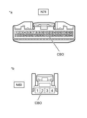
*a Front view of wire harness connector
(to Electric Vehicle Charger Assembly)
*b Front view of wire harness connector
(to EV Charger Lid Indicator Assembly)
Measure the resistance according to the value(s) in the table below.
Standard Resistance Tester Connection Condition Specified Condition N74-32 (CBO) - N60-2 (CBO) Power switch off Below 1 Ω N74-32 (CBO) or N60-2 (CBO) - Body ground and other terminals Power switch off 10 kΩ or higher -
Reconnect the N60 EV charger lid indicator assembly connector.
-
Reconnect the N74 electric vehicle charger assembly connector.
-
Install the EV charger duct.
Result Proceed to OK NG
OK
CAUSE ANALYSIS (ENVIRONMENT/USER RELATED CAUSE) Perform cause analysis in the order of "Environment" and "User" categories as specified in the following tables. Explain to the customer that, due to the temperature of the charging connector lock motor becoming high, to protect the charging connector lock motor, charging connector lock operation was prohibited. Wait 3 minutes or more after lock/unlock operation is prohibited, then resume inspection. Explain to the customer that as the entry function was disabled, the charging connector lock did not operate. Operating the charging connector lock when the entry function is disabled: If customize setting set to "Manual Lock": With all of the doors unlocked, connect the charging connector and press the charging connector lock/unlock switch (EV charger lid indicator assembly). If customize setting set to "Auto Lock" or "Auto Lock & Auto Unlock": Connect the charging connector. Explain to the customer that the charging connector lock may not operate if the charging port lid lock emergency release lever has been operated. Connect the charging connector with the push lifter of the EV charger lid switch assembly (charging lid courtesy switch) extended. Explain to the customer that the charging connector lock may not operate if the charging connector lock emergency release lever has been operated. Disconnect and then connect the charging connector. Explain to the customer that charging connector lock/unlock operation may be prohibited after the auxiliary battery has been replaced or the cable has been disconnected and reconnected to the negative (-) auxiliary battery terminal. Operate the charging connector lock/unlock again. Take appropriate action in accordance with the result of the cause analysis.
NG
REPAIR OR REPLACE HARNESS OR CONNECTOR
-
-
CHECK ELECTRIC VEHICLE CHARGER ASSEMBLY (PISW TERMINAL VOLTAGE)
CAUTION:
Be sure to wear insulated gloves.
-
Check that the service plug grip is not installed.
Note
After removing the service plug grip, do not turn the power switch on (READY), unless instructed by the repair manual because this may cause a malfunction.
-
Remove the EV charger duct.
-
Disconnect the N74 electric vehicle charger assembly connector.
-
Connect the cable to the negative (-) auxiliary battery terminal.
-
Turn the power switch on (IG).
-
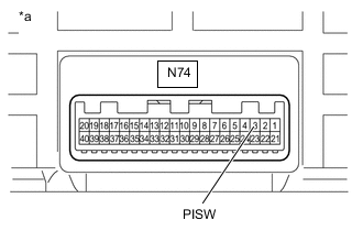
*a Component without harness connected
(Electric Vehicle Charger Assembly)
Measure the voltage according to the value(s) in the table below.
Standard Voltage Tester Connection Condition Specified Condition N74-3 (PISW) - Body ground Power switch on (IG) 3.572 to 4.730 V -
Turn the power switch off.
-
Disconnect the cable from the negative (-) auxiliary battery terminal.
-
Reconnect the N74 electric vehicle charger assembly connector.
-
Install the EV charger duct.
Result Proceed to OK NG
NG
REPLACE ELECTRIC VEHICLE CHARGER ASSEMBLY Click here
OK
-
-
INSPECT ELECTRIC VEHICLE CHARGER CABLE ASSEMBLY (FOR TYPE 1) (PISW)
Tech Tips
Perform the inspection with the electric vehicle charger cable assembly (for type 1) disconnected from the vehicle and external outlet.
-
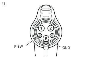
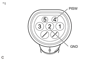
*1 Electric Vehicle Charger Cable Assembly (for Type 1) Measure the resistance according to the value(s) in the table below.
Standard Resistance Tester Connection Condition Specified Condition 3 (PISW) - 5 (GND) Latch release button (PI switch) pressed 430 to 530 Ω Latch release button (PI switch) not pressed 135 to 165 Ω -
Connect the electric vehicle charger cable assembly (for type 1) to the plug.
Tech Tips
Make sure not to connect it to the vehicle side charging inlet.
-
Measure the voltage according to the value(s) in the table below.
Standard Voltage Tester Connection Condition Specified Condition 3 (PISW) - 5 (GND) Latch release button (PI switch) pressed Below 1 V Latch release button (PI switch) not pressed Below 1 V -
Disconnect the electric vehicle charger cable assembly (for type 1) from the plug.
Result Proceed to OK NG
NG
REPLACE ELECTRIC VEHICLE CHARGER CABLE ASSEMBLY (FOR TYPE 1)
OK
-
-
CHECK HARNESS AND CONNECTOR (ELECTRIC VEHICLE CHARGER ASSEMBLY - CHARGING INLET (FOR TYPE 1))
CAUTION:
Be sure to wear insulated gloves.
-
Check that the service plug grip is not installed.
Note
After removing the service plug grip, do not turn the power switch on (READY), unless instructed by the repair manual because this may cause a malfunction.
-
Remove the EV charger duct.
-

Disconnect the N74 electric vehicle charger assembly connector.
-
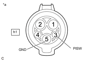
*a Inlet AC Charger Cable (for Type 1)
(Charging Inlet Side)
Measure the resistance according to the value(s) in the table below.
Standard Resistance Tester Connection Condition Specified Condition h1-3 (PISW) - h1-5 (GND) Power switch off 2.3 to 3.0 kΩ h1-3 (PISW) - Body ground Power switch off 2.3 to 3.0 kΩ -
Connect the cable to the negative (-) auxiliary battery terminal.
-
Turn the power switch on (IG).
-
Measure the voltage according to the value(s) in the table below.
Standard Voltage Tester Connection Condition Specified Condition h1-3 (PISW) - h1-5 (GND) Power switch on (IG) Below 1 V h1-3 (PISW) - Body ground Power switch on (IG) Below 1 V -
Turn the power switch off.
-
Disconnect the cable from the negative (-) auxiliary battery terminal.
-
Reconnect the N74 electric vehicle charger assembly connector.
-
Install the EV charger duct.
Result Proceed to OK NG
OK
CAUSE ANALYSIS (ENVIRONMENT/USER RELATED CAUSE) Perform cause analysis in the order of "Environment" and "User" categories as specified in the following tables. Explain to the customer that, due to the temperature of the charging connector lock motor becoming high, to protect the charging connector lock motor, charging connector lock operation was prohibited. Wait 3 minutes or more after lock/unlock operation is prohibited, then resume inspection. Explain to the customer that as the entry function was disabled, the charging connector lock did not operate. Operating the charging connector lock when the entry function is disabled: If customize setting set to "Manual Lock": With all of the doors unlocked, connect the charging connector and press the charging connector lock/unlock switch (EV charger lid indicator assembly). If customize setting set to "Auto Lock" or "Auto Lock & Auto Unlock": Connect the charging connector. Explain to the customer that the charging connector lock may not operate if the charging port lid lock emergency release lever has been operated. Connect the charging connector with the push lifter of the EV charger lid switch assembly (charging lid courtesy switch) extended. Explain to the customer that the charging connector lock may not operate if the charging connector lock emergency release lever has been operated. Disconnect and then connect the charging connector. Explain to the customer that charging connector lock/unlock operation may be prohibited after the auxiliary battery has been replaced or the cable has been disconnected and reconnected to the negative (-) auxiliary battery terminal. Operate the charging connector lock/unlock again. Take appropriate action in accordance with the result of the cause analysis.
NG
CHECK INLET AC CHARGER CABLE (FOR TYPE 1) (BODY GROUND TERMINAL CONNECTION CONDITION) Click here
-
-
CHECK ELECTRIC VEHICLE CHARGER ASSEMBLY (CPLT TERMINAL VOLTAGE)
CAUTION:
Be sure to wear insulated gloves.
-
Check that the service plug grip is not installed.
Note
After removing the service plug grip, do not turn the power switch on (READY), unless instructed by the repair manual because this may cause a malfunction.
-
Remove the EV charger duct.
-
Disconnect the N74 electric vehicle charger assembly connector.
-
Connect the cable to the negative (-) auxiliary battery terminal.
-
Turn the power switch on (IG).
-
*a Component without harness connected
(Electric Vehicle Charger Assembly)
Measure the voltage according to the value(s) in the table below.
Standard Voltage Tester Connection Condition Specified Condition N74-5 (CPLT) - Body ground Power switch on (IG) 0 to 1.5 V -
Turn the power switch off.
-
Disconnect the cable from the negative (-) auxiliary battery terminal.
-
Reconnect the N74 electric vehicle charger assembly connector.
-
Install the EV charger duct.
Result Proceed to OK NG
OK
GO TO CONTROL PILOT SIGNAL CIRCUIT Click here
NG
REPLACE ELECTRIC VEHICLE CHARGER ASSEMBLY Click here
-
-
CHECK INLET AC CHARGER CABLE (FOR TYPE 1) (BODY GROUND TERMINAL CONNECTION CONDITION)
-
Check the installation condition of the ground wire hA.
OK The ground wire is securely installed. Result Proceed to OK NG
NG
CONNECT SECURELY
OK
-
-
CHECK INLET AC CHARGER CABLE (FOR TYPE 1)
CAUTION:
Be sure to wear insulated gloves.
-
Check that the service plug grip is not installed.
Note
After removing the service plug grip, do not turn the power switch on (READY), unless instructed by the repair manual because this may cause a malfunction.
-
*1 Nh1 Disconnect the Nh1 inlet AC charger cable connector.
Note
If the Nh1 connector is disconnected with the auxiliary battery connected, P0D5615 may be detected. Check that the cable is disconnected from the negative (-) auxiliary battery terminal before proceeding work.
-
*a Inlet AC Charger Cable (for Type 1)
(Charging Inlet Side)
Measure the resistance according to the value(s) in the table below.
Standard Resistance Tester Connection Condition Specified Condition h1-3 (PISW) - h1-5 (GND) Power switch off 2.3 to 3.0 kΩ h1-3 (PISW) - Body ground Power switch off 2.3 to 3.0 kΩ -
Connect the cable to the negative (-) auxiliary battery terminal.
-
Turn the power switch on (IG).
-
Measure the voltage according to the value(s) in the table below.
Standard Voltage Tester Connection Condition Specified Condition h1-3 (PISW) - h1-5 (GND) Power switch on (IG) Below 1 V h1-3 (PISW) - Body ground Power switch on (IG) Below 1 V Note
Turning the power switch on (IG) with the inlet AC charger cable connector disconnected causes DTCs to be stored. Clear the DTCs after performing this inspection.
-
Turn the power switch off.
-
Disconnect the cable from the negative (-) auxiliary battery terminal.
-
Reconnect the Nh1 inlet AC charger cable connector.
Result Proceed to OK NG
OK
REPAIR OR REPLACE HARNESS OR CONNECTOR (INLET AC CHARGER CABLE (FOR TYPE 1) - ELECTRIC VEHICLE CHARGER ASSEMBLY)
NG
REPLACE INLET AC CHARGER CABLE (FOR TYPE 1) Click here
-
-
CHECK ELECTRIC VEHICLE CHARGER ASSEMBLY (CHARGING PORT LID OPEN AND CHARGING CONNECTOR LOCK UNLOCKED)
CAUTION:
Be sure to wear insulated gloves.
-
Check that the service plug grip is not installed.
Note
After removing the service plug grip, do not turn the power switch on (READY), unless instructed by the repair manual because this may cause a malfunction.
-
Remove the EV charger duct.
-
Connect the cable to the negative (-) auxiliary battery terminal.
-
Turn the power switch on (IG).
-
While carrying the electrical key transmitter sub-assembly, open the charging port lid.
-
Turn the power switch on (IG).
-
*a Component with harness connected
(Electric Vehicle Charger Assembly)
Measure the voltage according to the value(s) in the table below.
Tech Tips
Opening the charging port lid with all of the doors locked will unlock the charging connector lock.
Measure the voltage with the charging connector lock unlocked.
Standard Voltage Tester Connection Condition Specified Condition N74-30 (CBSW) - Body ground Power switch on (IG) 4.5 to 5.5 V N74-38 (CBMP) - Body ground Power switch on (IG) 0 to 1.5 V N74-18 (CBMN) - Body ground Power switch on (IG) 0 to 1.5 V N74-3 (PISW) - Body ground Power switch on (IG) 4.5 to 5.0 V N74-5 (CPLT) - Body ground Power switch on (IG) 0 to 1.5 V -
Connect the GTS to the DLC3.
-
Turn the GTS on.
-
Enter the following menus: Powertrain / Plug-in Control / Data List / Charging Connector Connect Status Voltage, Charging Connector Lock Pin Status, Charging Connector Lock Motor Unlock Direction Revolution Request Current, Charging Connector Lock Motor Lock Direction Revolution Request Current, Charging Current Duty from Charger, Time Cycle of Charging Current Duty from Charger.
Powertrain > Plug-in Control > Data ListTester Display Charging Connector Connect Status Voltage Charging Connector Lock Pin Status Charging Connector Lock Motor Unlock Direction Revolution Request Current Charging Connector Lock Motor Lock Direction Revolution Request Current Charging Current Duty from Charger Time Cycle of Charging Current Duty from Charger -
Read the value displayed on the GTS.
Powertrain > Plug-in Control > Data ListTester Display Measurement Item Normal Condition Charging Connector Connect Status Voltage PISW terminal voltage used for checking electric vehicle charger cable assembly connection condition
(PISW)
Electric vehicle charger cable assembly (for type 2) not connected: 4.00 to 4.50 V Charging Connector Lock Pin Status Charging connector lock pin status
(CBSW)
Charging connector lock pin not extended: Unlock Charging Connector Lock Motor Unlock Direction Revolution Request Current Output of current to operate charging connector lock motor in reverse
(CBMN)
Charging connector lock motor not operated: OFF Charging Connector Lock Motor Lock Direction Revolution Request Current Output of current to operate charging connector lock motor forward
(CBMP)
Charging connector lock motor not operated: OFF Charging Current Duty from Charger Duty value of CPLT signal generated from the electric vehicle charger assembly
(CPLT)
Electric vehicle charger cable assembly (for type 2) not connected: 0% Time Cycle of Charging Current Duty from Charger Duration of 1 cycle of CPLT signal
(CPLT)
Electric vehicle charger cable assembly (for type 2) not connected: 0 μs Tech Tips
The state of each terminal can be checked on the Data List.
-
Turn the power switch off.
-
Close the charging port lid.
-
Disconnect the cable from the negative (-) auxiliary battery terminal.
-
Install the EV charger duct.
Result Result Proceed to OK A NG
(CBSW)
B NG
(CBMP, CBMN)
C NG
(PISW)
D NG
(CPLT)
E
B
GO TO STEP 25 Click here
C
GO TO STEP 28 Click here
D
GO TO STEP 31 Click here
E
GO TO STEP 34 Click here
A
-
-
CHECK ELECTRIC VEHICLE CHARGER ASSEMBLY (CHARGING PORT LID OPEN AND CHARGING CONNECTOR LOCK LOCKED)
CAUTION:
Be sure to wear insulated gloves.
-
Check that the service plug grip is not installed.
Note
After removing the service plug grip, do not turn the power switch on (READY), unless instructed by the repair manual because this may cause a malfunction.
-
Remove the EV charger duct.
-
Connect the cable to the negative (-) auxiliary battery terminal.
-
Unlock all of the doors.
-
While carrying the electrical key transmitter sub-assembly, open the charging port lid.
-
Check that the charging connector lock is unlocked (lock pin is not extended).
Tech Tips
If the charging connector lock is locked (the lock pin is extended), unlock it using the charging connector lock emergency release lever.
-
Connect the electric vehicle charger cable assembly.
Tech Tips
Make sure that the charging connector is connected securely. If the charging connector is not connected securely, the charging connector lock may not operate properly.
-
Turn the power switch on (IG).
-
*a Component with harness connected
(Electric Vehicle Charger Assembly)
Measure the voltage according to the value(s) in the table below.
Tech Tips
Opening the charging port lid with all of the doors unlocked and then connecting the charging connector will lock the charging connector lock.
Standard Voltage Tester Connection Condition Specified Condition N74-38 (CBMP) - Body ground Power switch on (IG) 0 to 1.5 V N74-18 (CBMN) - Body ground Power switch on (IG) 0 to 1.5 V N74-3 (PISW) - Body ground Power switch on (IG) 0.5 to 4.5 V -
Connect the GTS to the DLC3.
-
Turn the GTS on.
-
Enter the following menus: Powertrain / Plug-in Control / Data List / Charging Connector Connect Status Voltage, Charging Connector Lock Pin Status, Charging Connector Lock Motor Unlock Direction Revolution Request Current, Charging Connector Lock Motor Lock Direction Revolution Request Current, Charging Current Duty from Charger, Time Cycle of Charging Current Duty from Charger.
Powertrain > Plug-in Control > Data ListTester Display Charging Connector Connect Status Voltage Charging Connector Lock Pin Status Charging Connector Lock Motor Unlock Direction Revolution Request Current Charging Connector Lock Motor Lock Direction Revolution Request Current Charging Current Duty from Charger Time Cycle of Charging Current Duty from Charger -
Read the value displayed on the GTS.
Powertrain > Plug-in Control > Data ListTester Display Measurement Item Normal Condition Charging Connector Connect Status Voltage PISW terminal voltage used for checking electric vehicle charger cable assembly connection condition
(PISW)
Electric vehicle charger cable assembly (for type 2) connected: 0.35 to 4.50 V Charging Connector Lock Pin Status Charging connector lock pin status
(CBSW)
Charging connector lock pin extended: Lock Charging Connector Lock Motor Unlock Direction Revolution Request Current Output of current to operate charging connector lock motor in reverse
(CBMN)
Charging connector lock motor not operated: OFF Charging Connector Lock Motor Lock Direction Revolution Request Current Output of current to operate charging connector lock motor forward
(CBMP)
Charging connector lock motor not operated: OFF Charging Current Duty from Charger Duty value of CPLT signal generated from the electric vehicle charger assembly
(CPLT)
Electric vehicle charger cable assembly (for type 2) connected: 5 to 39% Time Cycle of Charging Current Duty from Charger Duration of 1 cycle of CPLT signal
(CPLT)
CPLT (control pilot signal) generated: 951 to 1049 μs Tech Tips
The state of each terminal can be checked on the Data List.
-
Turn the power switch off.
-
Press the charging connector lock/unlock switch (EV charger lid indicator assembly) once to unlock the charging connector lock.
-
Disconnect the electric vehicle charger cable assembly.
-
Close the charging port lid.
-
Disconnect the cable from the negative (-) auxiliary battery terminal.
-
Install the EV charger duct.
Result Result Proceed to OK A NG
(CBSW)
B NG
(CBMP, CBMN)
C NG
(PISW)
D NG
(CPLT)
E
B
CHECK ELECTRIC VEHICLE CHARGER ASSEMBLY (CBSW TERMINAL VOLTAGE) Click here
C
CHECK ELECTRIC VEHICLE CHARGER ASSEMBLY (CBMP, CBMN TERMINAL VOLTAGE) Click here
D
CHECK ELECTRIC VEHICLE CHARGER ASSEMBLY (PISW TERMINAL VOLTAGE) Click here
E
CHECK ELECTRIC VEHICLE CHARGER ASSEMBLY (CPLT TERMINAL VOLTAGE) Click here
A
-
-
INSPECT CABLE EV CHARGER LOCK ASSEMBLY (FOR ELECTRIC VEHICLE CHARGER CABLE ASSEMBLY (TYPE 2))
Result Proceed to OK NG
OK
CAUSE ANALYSIS (ENVIRONMENT/USER RELATED CAUSE) Perform cause analysis in the order of "Environment" and "User" categories as specified in the following tables. Explain to the customer that, due to the temperature of the charging connector lock motor becoming high, to protect the charging connector lock motor, charging connector lock operation was prohibited. Wait 3 minutes or more after lock/unlock operation is prohibited, then resume inspection. Explain to the customer that the charging connector lock may not operate if the charging port lid lock emergency release lever has been operated. Connect the charging connector with the push lifter of the EV charger lid switch assembly (charging lid courtesy switch) extended. Explain to the customer that the charging connector lock may not operate if the charging connector lock emergency release lever has been operated. Disconnect and then connect the charging connector. Explain to the customer that charging connector lock/unlock operation may be prohibited after the auxiliary battery has been replaced or the cable has been disconnected and reconnected to the negative (-) auxiliary battery terminal. Operate the charging connector lock/unlock again. Explain to the customer that if the charging connector is not securely connected, the charging connector lock may attempt to lock several times unsuccessfully before stopping in the unlocked position. Disconnect the charging connector and then securely connect it to lock the charging connector lock. Take appropriate action in accordance with the result of the cause analysis.
NG
REPLACE CABLE EV CHARGER LOCK ASSEMBLY Click here
-
CHECK ELECTRIC VEHICLE CHARGER ASSEMBLY (CBSW TERMINAL VOLTAGE)
Result Proceed to OK NG CAUTION:
Be sure to wear insulated gloves.
-
Check that the service plug grip is not installed.
Note
After removing the service plug grip, do not turn the power switch on (READY), unless instructed by the repair manual because this may cause a malfunction.
-
Remove the EV charger duct.
-
Disconnect the N74 electric vehicle charger assembly connector.
-
Connect the cable to the negative (-) auxiliary battery terminal.
-
Turn the power switch on (IG).
-
*a Component without harness connected
(Electric Vehicle Charger Assembly)
Measure the voltage according to the value(s) in the table below.
Standard Voltage Tester Connection Condition Specified Condition N74-30 (CBSW) - Body ground Power switch on (IG) 4.5 to 5.5 V -
Turn the power switch off.
-
Disconnect the cable from the negative (-) auxiliary battery terminal.
-
Reconnect the N74 electric vehicle charger assembly connector.
-
Install the EV charger duct.
Result Proceed to OK NG
NG
REPLACE ELECTRIC VEHICLE CHARGER ASSEMBLY Click here
OK
-
-
INSPECT CABLE EV CHARGER LOCK ASSEMBLY (CHARGING CONNECTOR LOCK DETECTION SWITCH) (FOR ELECTRIC VEHICLE CHARGER CABLE ASSEMBLY (TYPE 2))
Result Proceed to OK NG
NG
REPLACE CABLE EV CHARGER LOCK ASSEMBLY Click here
OK
-
CHECK HARNESS AND CONNECTOR (ELECTRIC VEHICLE CHARGER ASSEMBLY - CABLE EV CHARGER LOCK ASSEMBLY (CBSW))
Result Proceed to OK NG CAUTION:
Be sure to wear insulated gloves.
-
Check that the service plug grip is not installed.
Note
After removing the service plug grip, do not turn the power switch on (READY), unless instructed by the repair manual because this may cause a malfunction.
-
Remove the EV charger duct.
-
Disconnect the N74 electric vehicle charger assembly connector.
-
Disconnect the N61 cable EV charger lock assembly connector.
-
*a Front view of wire harness connector
(to Electric Vehicle Charger Assembly)
*b Front view of wire harness connector
(to Cable EV Charger Lock Assembly)
Measure the resistance according to the value(s) in the table below.
Standard Resistance Tester Connection Condition Specified Condition N74-30 (CBSW) - N61-4 (CBSW) Power switch off Below 1 Ω N74-30 (CBSW) or N61-4 (CBSW) - Body ground and other terminals Power switch off 10 kΩ or higher -
Reconnect the N61 cable EV charger lock assembly connector.
-
Reconnect the N74 electric vehicle charger assembly connector.
-
Install the EV charger duct.
Result Proceed to OK NG
OK
CAUSE ANALYSIS (ENVIRONMENT/USER RELATED CAUSE) Perform cause analysis in the order of "Environment" and "User" categories as specified in the following tables. Explain to the customer that, due to the temperature of the charging connector lock motor becoming high, to protect the charging connector lock motor, charging connector lock operation was prohibited. Wait 3 minutes or more after lock/unlock operation is prohibited, then resume inspection. Explain to the customer that the charging connector lock may not operate if the charging port lid lock emergency release lever has been operated. Connect the charging connector with the push lifter of the EV charger lid switch assembly (charging lid courtesy switch) extended. Explain to the customer that the charging connector lock may not operate if the charging connector lock emergency release lever has been operated. Disconnect and then connect the charging connector. Explain to the customer that charging connector lock/unlock operation may be prohibited after the auxiliary battery has been replaced or the cable has been disconnected and reconnected to the negative (-) auxiliary battery terminal. Operate the charging connector lock/unlock again. Explain to the customer that if the charging connector is not securely connected, the charging connector lock may attempt to lock several times unsuccessfully before stopping in the unlocked position. Disconnect the charging connector and then securely connect it to lock the charging connector lock. Take appropriate action in accordance with the result of the cause analysis.
NG
REPAIR OR REPLACE HARNESS OR CONNECTOR
-
-
CHECK ELECTRIC VEHICLE CHARGER ASSEMBLY (CBMP, CBMN TERMINAL VOLTAGE)
Result Proceed to OK NG CAUTION:
Be sure to wear insulated gloves.
-
Check that the service plug grip is not installed.
Note
After removing the service plug grip, do not turn the power switch on (READY), unless instructed by the repair manual because this may cause a malfunction.
-
Remove the EV charger duct.
-
Disconnect the N74 electric vehicle charger assembly connector.
-
Connect the cable to the negative (-) auxiliary battery terminal.
-
Turn the power switch on (IG).
-
*a Component without harness connected
(Electric Vehicle Charger Assembly)
Measure the voltage according to the value(s) in the table below.
Standard Voltage Tester Connection Condition Specified Condition N74-38 (CBMP) - Body ground Power switch on (IG) 0 to 1.5 V N74-18 (CBMN) - Body ground Power switch on (IG) 0 to 1.5 V -
Turn the power switch off.
-
Disconnect the cable from the negative (-) auxiliary battery terminal.
-
Reconnect the N74 electric vehicle charger assembly connector.
-
Install the EV charger duct.
Result Proceed to OK NG
NG
REPLACE ELECTRIC VEHICLE CHARGER ASSEMBLY Click here
OK
-
-
INSPECT CABLE EV CHARGER LOCK ASSEMBLY (CHARGING CONNECTOR LOCK RELAY) (FOR ELECTRIC VEHICLE CHARGER CABLE ASSEMBLY (TYPE 2))
Result Proceed to OK NG
NG
REPLACE CABLE EV CHARGER LOCK ASSEMBLY Click here
OK
-
CHECK HARNESS AND CONNECTOR (ELECTRIC VEHICLE CHARGER ASSEMBLY - CABLE EV CHARGER LOCK ASSEMBLY (CBMP, CBMN))
Result Proceed to OK NG CAUTION:
Be sure to wear insulated gloves.
-
Check that the service plug grip is not installed.
Note
After removing the service plug grip, do not turn the power switch on (READY), unless instructed by the repair manual because this may cause a malfunction.
-
Remove the EV charger duct.
-
Disconnect the N74 electric vehicle charger assembly connector.
-
Disconnect the N61 cable EV charger lock assembly connector.
-
*a Front view of wire harness connector
(to Electric Vehicle Charger Assembly)
*b Front view of wire harness connector
(to Cable EV Charger Lock Assembly)
Measure the resistance according to the value(s) in the table below.
Standard Resistance Tester Connection Condition Specified Condition N74-38 (CBMP) - N61-10 (CBMP) Power switch off Below 1 Ω N74-38 (CBMP) or N61-10 (CBMP) - Body ground and other terminals Power switch off 10 kΩ or higher N74-18 (CBMN) - N61-3 (CBMN) Power switch off Below 1 Ω N74-18 (CBMN) or N61-3 (CBMN) - Body ground and other terminals Power switch off 10 kΩ or higher -
Reconnect the N61 cable EV charger lock assembly connector.
-
Reconnect the N74 electric vehicle charger assembly connector.
-
Install the EV charger duct.
Result Proceed to OK NG
OK
CAUSE ANALYSIS (ENVIRONMENT/USER RELATED CAUSE) Perform cause analysis in the order of "Environment" and "User" categories as specified in the following tables. Explain to the customer that, due to the temperature of the charging connector lock motor becoming high, to protect the charging connector lock motor, charging connector lock operation was prohibited. Wait 3 minutes or more after lock/unlock operation is prohibited, then resume inspection. Explain to the customer that the charging connector lock may not operate if the charging port lid lock emergency release lever has been operated. Connect the charging connector with the push lifter of the EV charger lid switch assembly (charging lid courtesy switch) extended. Explain to the customer that the charging connector lock may not operate if the charging connector lock emergency release lever has been operated. Disconnect and then connect the charging connector. Explain to the customer that charging connector lock/unlock operation may be prohibited after the auxiliary battery has been replaced or the cable has been disconnected and reconnected to the negative (-) auxiliary battery terminal. Operate the charging connector lock/unlock again. Explain to the customer that if the charging connector is not securely connected, the charging connector lock may attempt to lock several times unsuccessfully before stopping in the unlocked position. Disconnect the charging connector and then securely connect it to lock the charging connector lock. Take appropriate action in accordance with the result of the cause analysis.
NG
REPAIR OR REPLACE HARNESS OR CONNECTOR
-
-
CHECK ELECTRIC VEHICLE CHARGER ASSEMBLY (PISW TERMINAL VOLTAGE)
Result Proceed to OK NG CAUTION:
Be sure to wear insulated gloves.
-
Check that the service plug grip is not installed.
Note
After removing the service plug grip, do not turn the power switch on (READY), unless instructed by the repair manual because this may cause a malfunction.
-
Remove the EV charger duct.
-
Disconnect the N74 electric vehicle charger assembly connector.
-
Connect the cable to the negative (-) auxiliary battery terminal.
-
Turn the power switch on (IG).
-
*a Component without harness connected
(Electric Vehicle Charger Assembly)
Measure the voltage according to the value(s) in the table below.
Standard Voltage Tester Connection Condition Specified Condition N74-3 (PISW) - Body ground Power switch on (IG) 3.572 to 4.730 V -
Turn the power switch off.
-
Disconnect the cable from the negative (-) auxiliary battery terminal.
-
Reconnect the N74 electric vehicle charger assembly connector.
-
Install the EV charger duct.
Result Proceed to OK NG
NG
REPLACE ELECTRIC VEHICLE CHARGER ASSEMBLY Click here
OK
-
-
INSPECT ELECTRIC VEHICLE CHARGER CABLE ASSEMBLY (FOR TYPE 2) (PISW)
Tech Tips
Perform the inspection with the electric vehicle charger cable assembly (for type 2) disconnected from the vehicle and external outlet.
-
*1 Electric Vehicle Charger Cable Assembly (for Type 2) Measure the resistance according to the value(s) in the table below.
Standard Resistance Tester Connection Condition Specified Condition 4(PISW) - 2(GND) Always 646 to 714 Ω -
Connect the electric vehicle charger cable assembly (for type 2) to the plug.
Tech Tips
Make sure not to connect it to the vehicle side charging inlet.
-
Measure the voltage according to the value(s) in the table below.
Standard Voltage Tester Connection Condition Specified Condition 4(PISW) - 2(GND) Always Below 1 V -
Disconnect the electric vehicle charger cable assembly (for type 2) from the plug.
Result Proceed to OK NG
NG
REPLACE ELECTRIC VEHICLE CHARGER CABLE ASSEMBLY (FOR TYPE 2)
OK
-
-
CHECK HARNESS AND CONNECTOR (ELECTRIC VEHICLE CHARGER ASSEMBLY - CHARGING INLET (FOR TYPE 2))
CAUTION:
Be sure to wear insulated gloves.
-
Check that the service plug grip is not installed.
Note
After removing the service plug grip, do not turn the power switch on (READY), unless instructed by the repair manual because this may cause a malfunction.
-
Remove the EV charger duct.
-
Disconnect the N74 electric vehicle charger assembly connector.
-
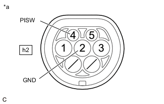
*a Inlet AC Charger Cable (for Type 2)
(Charging Inlet Side)
Measure the resistance according to the value(s) in the table below.
Standard Resistance Tester Connection Condition Specified Condition h2-4 (PISW) - h2-2 (GND) Power switch off 10 kΩ or more h2-4 (PISW) - Body ground Power switch off 10 kΩ or more h2-2 (GND) - Body ground Power switch off Below 1 Ω -
Connect the cable to the negative (-) auxiliary battery terminal.
-
Turn the power switch on (IG).
-
Measure the voltage according to the value(s) in the table below.
Standard Voltage Tester Connection Condition Specified Condition h2-4 (PISW) - h2-2 (GND) Power switch on (IG) Below 1 V h2-4 (PISW) - Body ground Power switch on (IG) Below 1 V -
Turn the power switch off.
-
Disconnect the cable from the negative (-) auxiliary battery terminal.
-
Reconnect the N74 electric vehicle charger assembly connector.
-
Install the EV charger duct.
Result Proceed to OK NG
OK
CAUSE ANALYSIS (ENVIRONMENT/USER RELATED CAUSE) Perform cause analysis in the order of "Environment" and "User" categories as specified in the following tables. Explain to the customer that, due to the temperature of the charging connector lock motor becoming high, to protect the charging connector lock motor, charging connector lock operation was prohibited. Wait 3 minutes or more after lock/unlock operation is prohibited, then resume inspection. Explain to the customer that the charging connector lock may not operate if the charging port lid lock emergency release lever has been operated. Connect the charging connector with the push lifter of the EV charger lid switch assembly (charging lid courtesy switch) extended. Explain to the customer that the charging connector lock may not operate if the charging connector lock emergency release lever has been operated. Disconnect and then connect the charging connector. Explain to the customer that charging connector lock/unlock operation may be prohibited after the auxiliary battery has been replaced or the cable has been disconnected and reconnected to the negative (-) auxiliary battery terminal. Operate the charging connector lock/unlock again. Explain to the customer that if the charging connector is not securely connected, the charging connector lock may attempt to lock several times unsuccessfully before stopping in the unlocked position. Disconnect the charging connector and then securely connect it to lock the charging connector lock. Take appropriate action in accordance with the result of the cause analysis.
NG
CHECK INLET AC CHARGER CABLE (FOR TYPE 2) (BODY GROUND TERMINAL CONNECTION CONDITION) Click here
-
-
CHECK ELECTRIC VEHICLE CHARGER ASSEMBLY (CPLT TERMINAL VOLTAGE)
Result Proceed to OK NG CAUTION:
Be sure to wear insulated gloves.
-
Check that the service plug grip is not installed.
Note
After removing the service plug grip, do not turn the power switch on (READY), unless instructed by the repair manual because this may cause a malfunction.
-
Remove the EV charger duct.
-
Disconnect the N74 electric vehicle charger assembly connector.
-
Connect the cable to the negative (-) auxiliary battery terminal.
-
Turn the power switch on (IG).
-
*a Component without harness connected
(Electric Vehicle Charger Assembly)
Measure the voltage according to the value(s) in the table below.
Standard Voltage Tester Connection Condition Specified Condition N74-5 (CPLT) - Body ground Power switch on (IG) 0 to 1.5 V -
Turn the power switch off.
-
Disconnect the cable from the negative (-) auxiliary battery terminal.
-
Reconnect the N74 electric vehicle charger assembly connector.
-
Install the EV charger duct.
Result Proceed to OK NG
OK
GO TO CONTROL PILOT SIGNAL CIRCUIT Click here
NG
REPLACE ELECTRIC VEHICLE CHARGER ASSEMBLY Click here
-
-
CHECK INLET AC CHARGER CABLE (FOR TYPE 2) (BODY GROUND TERMINAL CONNECTION CONDITION)
-
Check the installation condition of the ground wire hA.
OK The ground wire is securely installed. Result Proceed to OK NG
NG
CONNECT SECURELY
OK
-
-
CHECK INLET AC CHARGER CABLE (FOR TYPE 2)
CAUTION:
Be sure to wear insulated gloves.
-
Check that the service plug grip is not installed.
Note
After removing the service plug grip, do not turn the power switch on (READY), unless instructed by the repair manual because this may cause a malfunction.
-
*1 Nh1 Disconnect the Nh1 inlet AC charger cable connector.
-
*a Inlet AC Charger Cable (for Type 2)
(Charging Inlet Side)
Measure the resistance according to the value(s) in the table below.
Standard Resistance Tester Connection Condition Specified Condition h2-4 (PISW) - h2-2 (GND) Power switch off 10 kΩ or more h2-4 (PISW) - Body ground Power switch off 10 kΩ or more h2-2 (GND) - Body ground Power switch off Below 1 Ω -
Connect the cable to the negative (-) auxiliary battery terminal.
-
Turn the power switch on (IG).
-
Measure the voltage according to the value(s) in the table below.
Standard Voltage Tester Connection Condition Specified Condition h2-4 (PISW) - h2-2 (GND) Power switch on (IG) Below 1 V h2-4 (PISW) - Body ground Power switch on (IG) Below 1 V -
Turn the power switch off.
-
Disconnect the cable from the negative (-) auxiliary battery terminal.
-
Reconnect the Nh1 inlet AC charger cable connector.
Result Proceed to OK NG
OK
REPAIR OR REPLACE HARNESS OR CONNECTOR (INLET AC CHARGER CABLE (FOR TYPE 2) - ELECTRIC VEHICLE CHARGER ASSEMBLY)
NG
REPLACE INLET AC CHARGER CABLE (FOR TYPE 2) Click here
-