PLUG-IN CHARGE CONTROL SYSTEM Open in AC Line
WIRING DIAGRAM
Figure 1. for Electric Vehicle Charger Cable Assembly (Type 1)
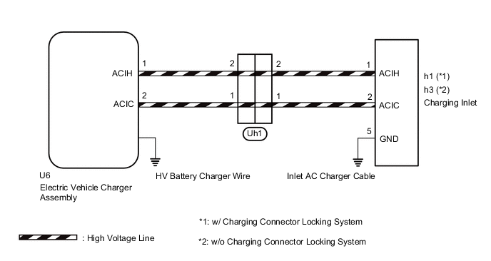
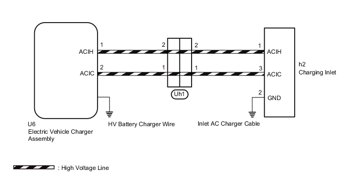
Figure 2. for Electric Vehicle Charger Cable Assembly (Type 2)
CAUTION / NOTICE / HINT
CAUTION:
-

Before the following operations are conducted, take precautions to prevent electric shock by turning the power switch off, wearing insulated gloves, and removing the service plug grip from HV battery.
-
Inspecting the high-voltage system
-
Disconnecting the low voltage connector of the inverter with converter assembly
-
Disconnecting the low voltage connector of the HV battery
-
Disconnecting the low voltage connector of the electric vehicle charger assembly
-
Disconnecting the low voltage connector of the solar energy control unit
-

To prevent electric shock, make sure to remove the service plug grip to cut off the high voltage circuit before servicing the vehicle.
-

After removing the service plug grip from the HV battery, put it in your pocket to prevent other technicians from accidentally reconnecting it while you are working on the high-voltage system.
-

*a Without waiting for 10 minutes After removing the service plug grip, wait for at least 10 minutes before touching any of the high-voltage connectors or terminals. After waiting for 10 minutes, check the voltage at the terminals in the inspection point in the inverter with converter assembly. The voltage should be 0 V before beginning work.
Tech Tips
Waiting for at least 10 minutes is required to discharge the high-voltage capacitor inside the inverter with converter assembly and the electric vehicle charger assembly.
Note
After turning the power switch off, waiting time may be required before disconnecting the cable from the negative (-) auxiliary battery terminal. Therefore, make sure to read the disconnecting the cable from the negative (-) auxiliary battery terminal notices before proceeding with work.
PROCEDURE
-
CHECK ELECTRIC VEHICLE CHARGER CABLE ASSEMBLY (CONNECTION CONDITION)
-
Visual inspection
-
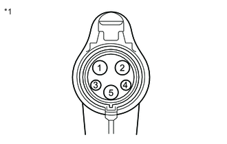
*1 Electric Vehicle Charger Cable Assembly (for Type 1)
(Charging Connector Side)
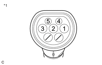
*1 Electric Vehicle Charger Cable Assembly (for Type 2)
(Charging Connector Side)
Check if any foreign matter is attached to the connecting part of the electric vehicle charger cable assembly.
Tech Tips
If there is foreign matter in the charging connector which prevents it from being securely connected, charging will not be performed.
-
-
Check the latch release button (PISW) (for electric vehicle charger cable assembly (Type 1))
-
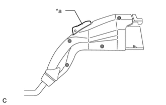
*a Latch Release Button (PISW) Check that the latch release button (PISW) can be pressed with no abnormal resistance.
-
-
Check connection
-
Check that the electric vehicle charger cable assembly and inlet AC charger cable (charging inlet side) can be connected smoothly.
OK The electric vehicle charger cable assembly and inlet AC charger cable (charging inlet side) connect smoothly. Tech Tips
If the result is not as specified, perform the following checks.
-
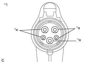
*1 Electric Vehicle Charger Cable Assembly (for Type 1)
(Charging Connector Side)
*a Terminal 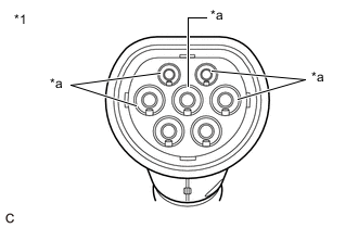
*1 Electric Vehicle Charger Cable Assembly (for Type 2)
(Charging Connector Side)
*a Terminal Check that the terminals of the electric vehicle charger cable assembly (charging connector side) are not bent or deformed.
OK The terminals are not bent or deformed. Tech Tips
If the result is not as specified, replace the electric vehicle charger cable assembly.
-
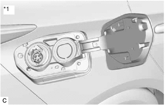
*1 Inlet AC Charger Cable (for Electric vehicle charger cable assembly (Type 1)) 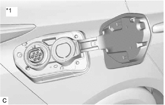
*1 Inlet AC Charger Cable (for Electric vehicle charger cable assembly (Type 2)) Check that the terminals of the inlet AC charger cable (charging inlet side) are not bent or deformed.
OK The terminals are not bent or deformed. Tech Tips
If the result is not as specified, replace the inlet AC charger cable.
Result Proceed to OK NG -
NG 
REPLACE MALFUNCTIONING PARTS
OK 
-
-
CHECK INLET AC CHARGER CABLE (CHARGING INLET - HV BATTERY CHARGER WIRE CONNECTOR)
CAUTION:
Be sure to wear insulated gloves.
-
Check that the service plug grip is not installed.
Note
After removing the service plug grip, do not turn the power switch on (READY), unless instructed by the repair manual because this may cause a malfunction.
-
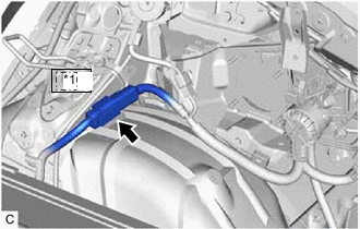
*1 Uh1 Disconnect the Uh1 inlet AC charger cable connector.
-
for Electric vehicle charger cable assembly (Type 1):
-
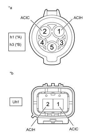
*A w/ Charging Connector Locking System *B w/o Charging Connector Locking System *a Inlet AC Charger Cable
(Charging Inlet)
*b Inlet AC Charger Cable
(to HV Battery Charger Wire)
Measure the resistance according to the value(s) in the table below.
Standard Resistance w/ Charging Connector Locking System Tester Connection Condition Specified Condition h1-1 (ACIH) - Uh1-2 (ACIH) Power switch off Below 1 Ω h1-2 (ACIC) - Uh1-1 (ACIC) Power switch off Below 1 Ω w/o Charging Connector Locking System Tester Connection Condition Specified Condition h3-1 (ACIH) - Uh1-2 (ACIH) Power switch off Below 1 Ω h3-2 (ACIC) - Uh1-1 (ACIC) Power switch off Below 1 Ω
-
-
for Electric vehicle charger cable assembly (Type 2):
-
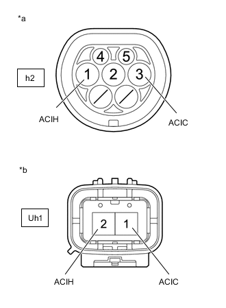
*a Inlet AC Charger Cable
(Charging Inlet)
*b Inlet AC Charger Cable
(to HV Battery Charger Wire)
Measure the resistance according to the value(s) in the table below.
Standard Resistance Tester Connection Condition Specified Condition h2-1 (ACIH) - Uh1-2 (ACIH) Power switch off Below 1 Ω h2-3 (ACIC) - Uh1-1 (ACIC) Power switch off Below 1 Ω
-
-
Reconnect the Uh1 inlet AC charger cable connector.
Result Proceed to OK NG
NG
REPLACE INLET AC CHARGER CABLE Click here
OK
-
-
CHECK HV BATTERY CHARGER WIRE (ELECTRIC VEHICLE CHARGER ASSEMBLY - INLET AC CHARGER CABLE)
CAUTION:
Be sure to wear insulated gloves.
-
Check that the service plug grip is not installed.
Note
After removing the service plug grip, do not turn the power switch on (READY), unless instructed by the repair manual because this may cause a malfunction.
-
Remove the rear under side cover RH.
-
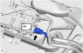
Disconnect the U6 electric vehicle charger assembly connector.
-
*1 Uh1 Disconnect the Uh1 inlet AC charger cable connector.
-
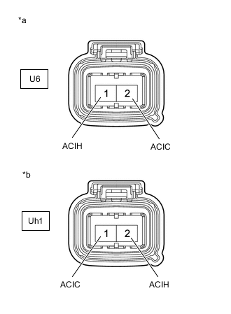
*a HV Battery Charger Wire
(Electric Vehicle Charger Assembly Side)
*b HV Battery Charger Wire
(Inlet AC Charger Cable Side)
Measure the resistance according to the value(s) in the table below.
Standard Resistance Tester Connection Condition Specified Condition U6-1(ACIH) - Uh1-2(ACIH) Power switch off Below 1 Ω U6-2(ACIC) - Uh1-1(ACIC) Power switch off Below 1 Ω -
Reconnect the Uh1 inlet AC charger cable connector.
-
Reconnect the U6 electric vehicle charger assembly connector.
-
Install the rear under side cover RH.
Result Proceed to OK NG
OK
REPLACE ELECTRIC VEHICLE CHARGER ASSEMBLY Click here
NG
REPLACE HV BATTERY CHARGER WIRE Click here
-