PLUG-IN CHARGE CONTROL SYSTEM, Diagnostic DTC:P1CE931, P1CE996
| DTC Code | DTC Name |
|---|---|
| P1CE931 | Charger Cooling Fan Revolution Signal No Signal |
| P1CE996 | Charger Cooling Fan Revolution Signal Component Internal Failure |
DTC SUMMARY
-
MALFUNCTION DESCRIPTION
The charge control ECU built into the electric vehicle charger assembly monitors the charger cooling blower speed and stores DTCs if the charger cooling blower speed becomes abnormal.
The cause of this malfunction may be one of the following:
-
Electric vehicle charger assembly (charge control ECU) internal malfunction
-
Charger cooling blower malfunction (open circuit/temporary interruption, foreign matter, charger cooling blower speed sensor malfunction, etc.)
-
Charger cooling blower operation command circuit malfunction (between the electric vehicle charger assembly and charger cooling blower)
Charger cooling blower circuit malfunction
-
-
INSPECTION DESCRIPTION
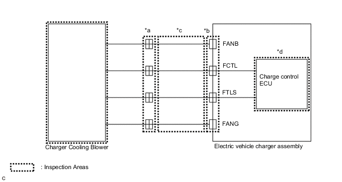
System Diagram Range Inspection Content Reason *a Check whether the charger cooling blower connector is connected. Improperly connected charger cooling blower connector. *b Check whether the electric vehicle charger assembly connector is connected. Improperly connected electric vehicle charger assembly connector. *c Check for an open or short in the wire harness. Open circuit or short circuit in the wire harness. *d Replace electric vehicle charger assembly Electric vehicle charger assembly internal malfunction
DESCRIPTION
| DTC No. | Detection Item | DTC Detection Condition | Trouble Area | MIL | Warning Indicate |
|---|---|---|---|---|---|
| P1CE931 | Charger Cooling Fan Revolution Signal No Signal | The insufficient rotation counter is more than the judgment value. (1 trip detection logic) |
|
Does not come on | Master Warning Light: Comes on |
| P1CE996 | Charger Cooling Fan Revolution Signal Component Internal Failure | The cooling fan speed is lower than the threshold for 10 seconds or more. (1 trip detection logic) |
|
Does not come on | Master Warning Light: Comes on |
| DTC No. | Data List |
|---|---|
| P1CE931 |
|
| P1CE996 |
CONFIRMATION DRIVING PATTERN
Tech Tips
After repair has been completed, clear the DTC and then check that the vehicle has returned to normal by performing the following All Readiness check procedure.
-
Connect the GTS to the DLC3.
-
Turn the power switch on (IG) and turn the GTS on.
-
Clear the DTCs (even if no DTCs are stored, perform the clear DTC procedure).
-
Enter the following menus: Powertrain / Hybrid Control / Data List.
-
Check that "Hybrid Battery SOC" shows 70% or less.
-
Turn the power switch off and wait for 2 minutes or more.
-
Connect the electric vehicle charger cable assembly, and plug-in charge the vehicle for 30 minutes or more.
Tech Tips
If "PFC Boosting Circuit Temperature" or "DC/DC Converter Temperature (for Charging)" becomes 55°C (131°F) or more, the cooling fun rotates and a malfunction could be detected.
-
Disconnect the electric vehicle charger cable assembly and wait for 10 seconds or more.
-
Turn the power switch on (IG) and turn the GTS on.
-
Enter the following menus: Powertrain / Plug-in Control / Utility / All Readiness.
-
Check the DTC judgment result.
Tech Tips
-
If the judgment result shows NORMAL, the system is normal.
-
If the judgment result shows ABNORMAL, the system has a malfunction.
-
If the judgment result shows INCOMPLETE or N/A, perform driving pattern again.
-
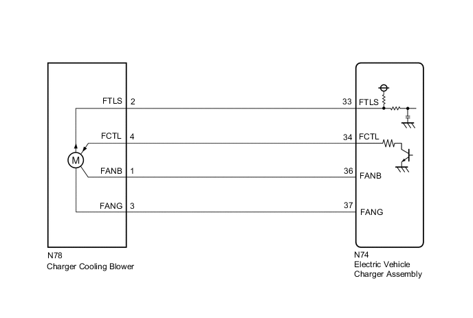
WIRING DIAGRAM
CAUTION / NOTICE / HINT
CAUTION:
-

Before the following operations are conducted, take precautions to prevent electric shock by turning the power switch off, wearing insulated gloves, and removing the service plug grip from HV battery.
-
Inspecting the high-voltage system
-
Disconnecting the low voltage connector of the inverter with converter assembly
-
Disconnecting the low voltage connector of the HV battery
-
Disconnecting the low voltage connector of the electric vehicle charger assembly
-
Disconnecting the low voltage connector of the solar energy control unit
-

To prevent electric shock, make sure to remove the service plug grip to cut off the high voltage circuit before servicing the vehicle.
-

After removing the service plug grip from the HV battery, put it in your pocket to prevent other technicians from accidentally reconnecting it while you are working on the high-voltage system.
-

*a Without waiting for 10 minutes After removing the service plug grip, wait for at least 10 minutes before touching any of the high-voltage connectors or terminals. After waiting for 10 minutes, check the voltage at the terminals in the inspection point in the inverter with converter assembly. The voltage should be 0 V before beginning work.
Tech Tips
Waiting for at least 10 minutes is required to discharge the high-voltage capacitor inside the inverter with converter assembly and the electric vehicle charger assembly.
Note
After turning the power switch off, waiting time may be required before disconnecting the cable from the negative (-) auxiliary battery terminal. Therefore, make sure to read the disconnecting the cable from the negative (-) auxiliary battery terminal notices before proceeding with work.
PROCEDURE
-
CHECK DTC OUTPUT (PLUG-IN CONTROL)
-
Connect the GTS to the DLC3.
-
Turn the power switch on (IG).
-
Enter the following menus: Powertrain / Plug-in Control / Trouble Codes.
-
Check for DTCs.
Powertrain > Plug-in Control > Trouble CodesResult Result Proceed to P1CE931 or P1CE996 only is output, or DTCs except the ones in the table below are also output. A DTCs of plug-in charge control system in the tables below are output. B Malfunction Content System Relevant DTC Microcomputer malfunction Plug-in charge control system P060B49 Plug-in Control Module A/D Processing Internal Electronic Failure Communication system malfunction P0E5E87 Plug-in Control Module Processor from Hybrid/EV Battery Charger Control Module Processor Missing Message U029387 Lost Communication with Hybrid/EV Powertrain Control Module Missing Message U115087 Lost Communication with Hybrid Powertrain Control Module (Hybrid/EV Battery Local Bus) Missing Message Tech Tips
-
P1CE931 and P1CE996 may be output as a result of the malfunction indicated by the DTCs above.
-
The chart above is listed in inspection order of priority.
-
Check DTCs that are output at the same time by following the listed order. (The main cause of the malfunction can be determined without performing unnecessary inspections.)
-
-
Turn the power switch off.
B 
GO TO DTC CHART (PLUG-IN CHARGE CONTROL SYSTEM) Click here
A 
-
-
PERFORM ACTIVE TEST USING GTS (ACTIVATE THE CHARGER COOLING FAN)
-
Connect the GTS to the DLC3.
-
Turn the power switch on (IG).
-
Enter the following menus: Powertrain / Plug-in Control / Active Test / Activate the Charger Cooling Fan.
Powertrain > Plug-in Control > Active TestTester Display Activate the Charger Cooling Fan -
Perform the "Activate the Charger Cooling Fan" Active Test.
-
Check that the charger cooling blower operates, air is sucked into the inlet duct and the operation sound is normal.
Result The charger cooling blower operates. -
Turn the power switch off.
Result Proceed to OK NG
NG 
CHECK CONNECTOR CONNECTION CONDITION (CHARGER COOLING BLOWER CONNECTOR) Click here
OK
-
-
CHECK CHARGER COOLING BLOWER (CHECK WAVEFORM)
-
Remove the EV charger duct.
-
Connect the GTS to the DLC3.
-
Turn the power switch on (IG).
-
Enter the following menus: Powertrain / Plug-in Control / Active Test / Activate the Charger Cooling Fan.
Powertrain > Plug-in Control > Active TestTester Display Activate the Charger Cooling Fan -
Perform the "Activate the Charger Cooling Fan" Active Test.
-
Connect an oscilloscope between the electric vehicle charger assembly terminals specified in the table below.
-
Measure the waveform during the Active Test.
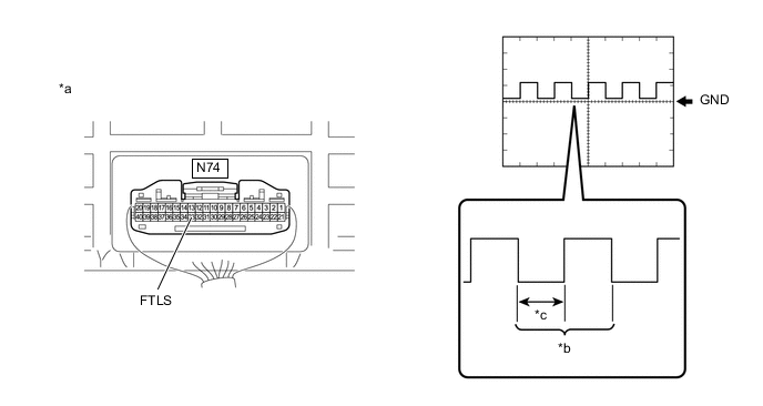
*a Component with harness connected
(Electric Vehicle Charger Assembly)
*b Waveform *c Waveform with Low Range - - Item Contents Terminal N74-33 (FTLS) - Body ground Equipment Setting 1 V/DIV., 5 ms/DIV. Condition Charger cooling fan operating Tech Tips
The wavelength will vary with the operating speed of the cooling fan.
Result Result Proceed to The waveform can be measured and the following conditions are met:
-
Waveform is 1.5 to 4.0 ms.
-
Duty ratio (waveform with low range) is 40 to 60%.
A Other than above B -
-
Turn the power switch off.
-
Install the EV charger duct.
B
REPLACE CHARGER COOLING BLOWER Click here
A
-
-
CHECK HARNESS AND CONNECTOR (CHARGER COOLING BLOWER - ELECTRIC VEHICLE CHARGER ASSEMBLY)
CAUTION:
Be sure to wear insulated gloves.
-
Check that the service plug grip is not installed.
Note
After removing the service plug grip, do not turn the power switch on (READY), unless instructed by the repair manual because this may cause a malfunction.
-
Remove the EV charger duct.
-

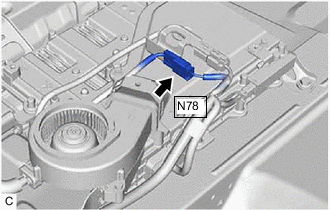
Disconnect the N78 charger cooling blower connector.
-

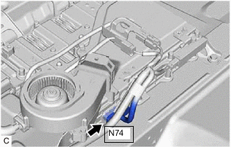
Disconnect the N74 electric vehicle charger assembly connector.
-
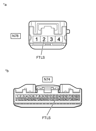
*a Front view of wire harness connector
(to Charger Cooling Blower)
*b Front view of wire harness connector
(to Electric Vehicle Charger Assembly)
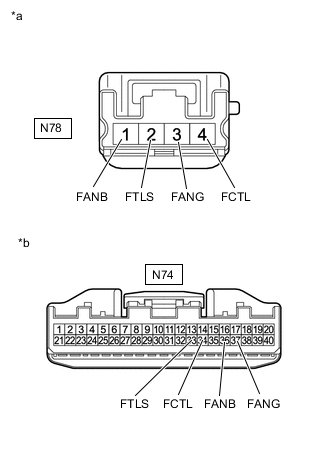
Measure the resistance according to the value(s) in the table below.
Standard Resistance Tester Connection Condition Specified Condition N78-2 (FTLS) - N74-33 (FTLS) IG OFF Below 1 Ω N78-2 (FTLS) and N74-33 (FTLS) - Body ground and other terminals IG OFF 10 kΩ or higher -
Reconnect the N74 electric vehicle charger assembly connector.
-
Reconnect the N78 charger cooling blower connector.
-
Install the EV charger duct.
Result Proceed to OK NG
OK
REPLACE ELECTRIC VEHICLE CHARGER ASSEMBLY Click here
NG
REPAIR OR REPLACE HARNESS OR CONNECTOR
-
-
CHECK CONNECTOR CONNECTION CONDITION (CHARGER COOLING BLOWER CONNECTOR)
-
Remove the EV charger duct.
-
Check the connector connection for the N78 charger cooling blower connector.
-
Disconnect the N78 charger cooling blower connector.
-
Check the contact pressure of each terminal of the N78 charger cooling blower connector and check for foreign matter or arc marks on the terminals.
Result Result Proceed to The terminals are connected securely and there are no contact problems. There is neither foreign matter nor ark marks. A The terminals are not connected securely and there is a contact problem. There is any of foreign matter or ark marks. B The terminals are not connected securely and there is a contact problem. There is neither foreign matter nor ark marks. C The terminals are connected securely and there are no contact problems. There is any of foreign matter or ark marks. B -
Reconnect the N78 charger cooling blower connector.
-
Install the EV charger duct.
B
REPLACE MALFUNCTIONING PARTS
C
CONNECT SECURELY
A
-
-
CHECK CONNECTOR CONNECTION CONDITION (ELECTRIC VEHICLE CHARGER ASSEMBLY CONNECTOR)
CAUTION:
Be sure to wear insulated gloves.
-
Check that the service plug grip is not installed.
Note
After removing the service plug grip, do not turn the power switch on (READY), unless instructed by the repair manual because this may cause a malfunction.
-
Remove the EV charger duct.
-
Check the connector connection for the N74 electric vehicle charger assembly connector.
-
Disconnect the N74 electric vehicle charger assembly connector.
-
Check the contact pressure of each terminal of the N74 electric vehicle charger assembly connector and check for foreign matter or arc marks on the terminals.
Result Result Proceed to The terminals are connected securely and there are no contact problems. There is neither foreign matter nor ark marks. A The terminals are not connected securely and there is a contact problem. There is any of foreign matter or ark marks. B The terminals are not connected securely and there is a contact problem. There is neither foreign matter nor ark marks. C The terminals are connected securely and there are no contact problems. There is any of foreign matter or ark marks. B -
Reconnect the N74 electric vehicle charger assembly connector.
-
Install the EV charger duct.
B
REPLACE MALFUNCTIONING PARTS
C
CONNECT SECURELY
A
-
-
CHECK CHARGER COOLING BLOWER (VISUALLY CHECK)
-
Remove the charger cooling blower.
-
Check the fan rotating part of the charger cooling blower for foreign matter.
Result There is no foreign matter or the charger cooling blower is not clogged with foreign matter. -
Install the charger cooling blower.
Result Proceed to OK NG
NG
REPLACE CHARGER COOLING BLOWER Click here
OK
-
-
CHECK HARNESS AND CONNECTOR (CHARGER COOLING BLOWER - ELECTRIC VEHICLE CHARGER ASSEMBLY)
CAUTION:
Be sure to wear insulated gloves.
-
Check that the service plug grip is not installed.
Note
After removing the service plug grip, do not turn the power switch on (READY), unless instructed by the repair manual because this may cause a malfunction.
-
Remove the EV charger duct.
-
Disconnect the N78 charger cooling blower connector.
-
Disconnect the N74 electric vehicle charger assembly connector.
-
*a Front view of wire harness connector
(to Charger Cooling Blower)
*b Front view of wire harness connector
(to Electric Vehicle Charger Assembly)
Measure the resistance according to the value(s) in the table below.
Standard Resistance Tester Connection Condition Specified Condition N78-2 (FTLS) - N74-33 (FTLS) IG OFF Below 1 Ω N78-4 (FCTL) - N74-34 (FCTL) IG OFF Below 1 Ω N78-1 (FANB) - N74-36 (FANB) IG OFF Below 1 Ω N78-3 (FANG) - N74-37 (FANG) IG OFF Below 1 Ω N78-2 (FTLS) and N74-33 (FTLS) - Body ground and other terminals IG OFF 10 kΩ or higher N78-4 (FCTL) and N74-34 (FCTL) - Body ground and other terminals IG OFF 10 kΩ or higher N78-1 (FANB) and N74-36 (FANB) - Body ground and other terminals IG OFF 10 kΩ or higher N78-3 (FANG) and N74-37 (FANG) - Body ground and other terminals IG OFF 10 kΩ or higher -
Reconnect the N74 electric vehicle charger assembly connector.
-
Reconnect the N78 charger cooling blower connector.
-
Install the EV charger duct.
Result Proceed to OK NG
NG
REPAIR OR REPLACE HARNESS OR CONNECTOR
OK
-
-
CHECK ELECTRIC VEHICLE CHARGER ASSEMBLY (CHECK VOLTAGE)
-
Remove the EV charger duct.
-
Connect the GTS to the DLC3.
-
Turn the power switch on (IG).
-
Enter the following menus: Powertrain / Plug-in Control / Active Test / Activate the Charger Cooling Fan.
Powertrain > Plug-in Control > Active TestTester Display Activate the Charger Cooling Fan -
Perform the "Activate the Charger Cooling Fan" Active Test.
-
*a Component with harness connected
(Electric Vehicle Charger Assembly)
Measure the voltage according to the value(s) in the table below.
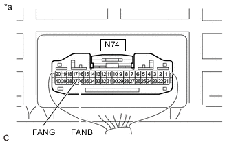
Standard Voltage Tester Connection Condition Specified Condition N74-36 (FANB) - N74-37 (FANG) Cooling fan operating 11 to 14 V -
Turn the power switch off.
-
Install the EV charger duct.
Result Proceed to OK NG
NG
REPLACE ELECTRIC VEHICLE CHARGER ASSEMBLY Click here
OK
-
-
CHECK CHARGER COOLING BLOWER (CHECK WAVEFORM)
-
Remove the EV charger duct.
-
Connect the GTS to the DLC3.
-
Turn the power switch on (IG).
-
Enter the following menus: Powertrain / Plug-in Control / Active Test / Activate the Charger Cooling Fan.
Powertrain > Plug-in Control > Active TestTester Display Activate the Charger Cooling Fan -
Perform the "Activate the Charger Cooling Fan" Active Test.
-
Connect an oscilloscope between the electric vehicle charger assembly terminals specified in the table below.
-
Measure the waveform during the Active Test.
*a Component with harness connected
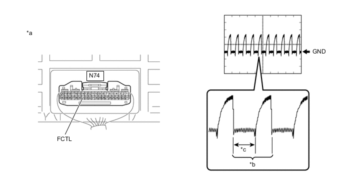
(Electric Vehicle Charger Assembly)
*b Waveform *c Waveform with Low Range - - Item Contents Terminal N74-34 (FCTL) - Body ground Equipment Setting 1 V/DIV., 50 μs/DIV. Condition Charger cooling fan operating Tech Tips
The waveform will vary depending on the content of the digital communication (digital signal).
Result Result Proceed to The waveform can be measured and the following conditions are met:
-
Waveform is 44 to 55 μs.
-
Duty ratio (waveform with low range) is 45 to 100%.
A Other than above B -
-
Turn the power switch off.
-
Install the EV charger duct.
A
REPLACE CHARGER COOLING BLOWER Click here
B
REPLACE ELECTRIC VEHICLE CHARGER ASSEMBLY Click here
-