CHARGE INLET INSPECTION
PROCEDURE
-
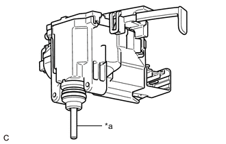
INSPECT CABLE EV CHARGER LOCK ASSEMBLY (for Type A)
-
Visual inspection
-
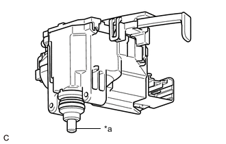
*a Lock Pin Check that there is no foreign matter on the lock pin of the cable EV charger lock assembly.
Tech Tips
-
If there is foreign matter on the lock pin, remove it.
-
If the foreign matter cannot be removed, replace the cable EV charger lock assembly.
-
-
Check that the lock pin of the cable EV charger lock assembly is not bent, damaged or deformed.
Tech Tips
If the lock pin of the cable EV charger lock assembly is bent, damaged or deformed, replace the cable EV charger lock assembly.
-
-
Check the operation of the lock pin.
-
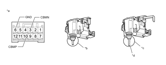
Apply auxiliary battery voltage to the terminals of the connector and check that the lock pin operates.
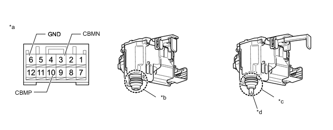
*a Component without harness connected
(Cable EV Charger Lock Assembly)
*b Unlocked *c Locked *d Lock Pin OK Measurement Condition Specified Condition Auxiliary Battery positive (+) → 10 (CBMP)
Auxiliary Battery negative (-) → 6 (GND)
Locks Auxiliary Battery positive (+) → 3 (CBMN)
Auxiliary Battery negative (-) → 6 (GND)
Unlocks Note
-
Apply auxiliary battery voltage for less than 2 or 3 seconds.
-
If voltage is applied for an excessive amount of time, the cable EV charger lock assembly may be damaged.
-
Confirm the current position of the lock pin before applying auxiliary battery voltage.
-
When the lock pin is in the locked position, perform the unlock operation inspection.
-
When the lock pin is in the unlocked position, perform the lock operation inspection.
Tech Tips
If the result is not as specified, replace the cable EV charger lock assembly.
-
-
-
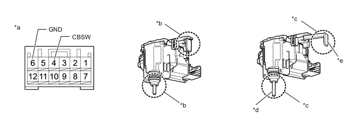
Inspect the lock pin position detection circuit.
-
Measure the resistance according to the value(s) in the table below.
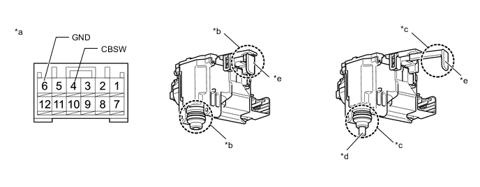
*a Component without harness connected
(Cable EV Charger Lock Assembly)
*b Unlocked *c Locked *d Lock Pin *e Lock Release Lever - - Standard Resistance Tester Connection Condition Specified Condition 4 (CBSW) - 6 (GND) Locks Below 1 Ω Unlocks 10 kΩ or higher Note
The lock release lever moves when the lock pin changes from locked to unlocked or from unlocked to locked.
Tech Tips
If the result is not as specified, replace the cable EV charger lock assembly.
-
-
Inspect the power supply circuit of the fuel lid lock with motor assembly
-
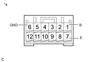
*a Component without harness connected
(Cable EV Charger Lock Assembly)
Measure the resistance according to the value(s) in the table below.
Standard Resistance Tester Connection Condition Specified Condition 7(E) - 6(GND) Auxiliary battery voltage not applied between terminals 10 (CBMP) - 6 (GND) Below 1 Ω 1(B) - 6(GND) Auxiliary battery voltage applied between terminals 3 (CBMN) - 6 (GND) Tech Tips
If the result is not as specified, replace the cable EV charger lock assembly.
-
-
-
INSPECT CABLE EV CHARGER LOCK ASSEMBLY (for Type B)
-
Visual inspection
-
*a Lock Pin Check that there is no foreign matter on the lock pin of the cable EV charger lock assembly.
Tech Tips
-
If there is foreign matter on the lock pin, remove it.
-
If the foreign matter cannot be removed, replace the cable EV charger lock assembly.
-
-
Check that the lock pin of the cable EV charger lock assembly is not bent, damaged or deformed.
Tech Tips
If the lock pin of the cable EV charger lock assembly is bent, damaged or deformed, replace the cable EV charger lock assembly.
-
-
Check the operation of the lock pin.
-
Apply auxiliary battery voltage to the terminals of the connector and check that the lock pin operates.
*a Component without harness connected
(Cable EV Charger Lock Assembly)
*b Unlocked *c Locked *d Lock Pin OK Measurement Condition Specified Condition Auxiliary Battery positive (+) → 10 (CBMP)
Auxiliary Battery negative (-) → 6 (GND)
Locks Auxiliary Battery positive (+) → 3 (CBMN)
Auxiliary Battery negative (-) → 6 (GND)
Unlocks Note
-
Apply auxiliary battery voltage for less than 2 or 3 seconds.
-
If voltage is applied for an excessive amount of time, the cable EV charger lock assembly may be damaged.
-
Confirm the current position of the lock pin before applying auxiliary battery voltage.
-
When the lock pin is in the locked position, perform the unlock operation inspection.
-
When the lock pin is in the unlocked position, perform the lock operation inspection.
Tech Tips
If the result is not as specified, replace the cable EV charger lock assembly.
-
-
-
Inspect the lock pin position detection circuit.
-
Measure the resistance according to the value(s) in the table below.
*a Component without harness connected
(Cable EV Charger Lock Assembly)
*b Unlocked *c Locked *d Lock Pin *e Lock Release Lever - - Standard Resistance Tester Connection Condition Specified Condition 4 (CBSW) - 6 (GND) Locks Below 1 Ω Unlocks 10 kΩ or higher Note
The lock release lever moves when the lock pin changes from locked to unlocked or from unlocked to locked.
Tech Tips
If the result is not as specified, replace the cable EV charger lock assembly.
-
-
Inspect the power supply circuit of the fuel lid lock with motor assembly
-
*a Component without harness connected
(Cable EV Charger Lock Assembly)
Measure the resistance according to the value(s) in the table below.
Standard Resistance Tester Connection Condition Specified Condition 7(E) - 6(GND) Auxiliary battery voltage not applied between terminals 10 (CBMP) - 6 (GND) Below 1 Ω 1(B) - 6(GND) Auxiliary battery voltage applied between terminals 3 (CBMN) - 6 (GND) Tech Tips
If the result is not as specified, replace the cable EV charger lock assembly.
-
-