PLUG-IN CHARGE CONTROL SYSTEM TERMINALS OF ECU
-
ELECTRIC VEHICLE CHARGER ASSEMBLY
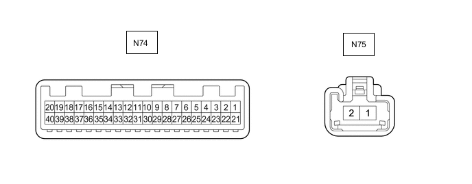
Terminal No.
(Symbol)
Wiring Color Input/Output Terminal Description Condition Specified Condition N74-1 (CHEN) - Body ground G OUT Charging permission signal Power switch on (IG) Below 1.5 V N74-3 (PISW) - Body ground R IN Charging connector connection signal
(for electric vehicle charger cable assembly (Type 1))
Power switch on (IG), electric vehicle charger cable assembly not connected 4.2 to 4.8 V Power switch on (IG), electric vehicle charger cable assembly connected and latch release button (PI switch) pressed 2.5 to 3.1 V Power switch on (IG), electric vehicle charger cable assembly connected and latch release button (PI switch) not pressed 1.2 to 1.8 V Charging connector connection signal
(for electric vehicle charger cable assembly (Type 2))
Power switch on (IG), electric vehicle charger cable assembly not connected 4.2 to 4.8 V Power switch on (IG), electric vehicle charger cable assembly connected (13A) 3.8 to 4.4 V Power switch on (IG), electric vehicle charger cable assembly connected (20 A)
(Genuine charging cable)
3.1 to 3.7 V Power switch on (IG), electric vehicle charger cable assembly connected (32 A) 1.7 to 2.3 V N74-5 (CPLT) - Body ground L IN/OUT Charge voltage judgment and allowable amperage recognition signals Plug-in charging Pulse generation
(Waveform 1)
Power switch on (IG), electric vehicle charger cable assembly not connected 2603 to 2877 Ω N74-6 (IGCT) - Body ground GR IN IGCT power source Power switch on (IG) 11 to 14 V N74-7 (INL3) - Body ground P OUT SOC indicator 3 Power switch on (IG), charging indicator turned off 0 to 1.5 V Illumination conditions for SOC indicator (indicator light assembly) (3rd indicator) met 5.0 to 12.5 V N74-9 (PTMS) - Body ground R IN Timer charging switch signal Power switch on (IG), timer charging switch pressed 0 to 1.5 V Power switch on (IG), timer charging switch not pressed 11 to 14 V N74-10 (LDLP) - Body ground SB OUT Charging inlet light Power switch on (IG), Charging port lid closed 0 to 1.5 V Power switch on (IG), charging port lid open, conditions to turn off indicator met 11 to 14 V Power switch on (IG), charging port lid open, conditions to turn on indicator met 0 to 4.0 V N74-11 (PIL) - Body ground GR OUT Charging indicator light Power switch on (IG), charging indicator light not illuminated 0 to 1.5 V Plug-in charging being performed, charging indicator light illuminated 8.0 to 14.0 V N74-16 (CA4L) - Body ground W IN/OUT CAN communication signal Power switch on (IG) Pulse generation
(Waveform 2)
N74-17 (CA4H) - Body ground LG IN/OUT CAN communication signal Power switch on (IG) N74-18 (CBMN) - Body ground*1 P OUT Charging connector lock motor reverse operation Power switch on (IG), charging connector lock/charging port lid lock not operating 0 to 1.5 V Power switch on (IG), charging connector lock/charging port lid lock operating (unlock) 10.5 to 14.0 V N74-19 (CA1L) - Body ground W IN/OUT CAN communication signal Power switch on (IG) Pulse generation
(Waveform 3)
N74-20 (CA1H) - Body ground L IN/OUT CAN communication signal Power switch on (IG) N74-26 (INL1) - Body ground W OUT SOC indicator 1 Power switch on (IG), charging indicator turned off 0 to 1.5 V Illumination conditions for SOC indicator (indicator light assembly) (1st indicator) met 5.0 to 12.5 V N74-27 (INL2) - Body ground SB OUT SOC indicator 2 Power switch on (IG), charging indicator turned off 0 to 1.5 V Illumination conditions for SOC indicator (indicator light assembly) (2nd indicator) met 5.0 to 12.5 V N74-28 (LDSW) - Body ground BE IN Charging lid courtesy switch signal Power switch on (IG), charging port lid closed 0 to 1.5 V Power switch on (IG), charging port lid open 11 to 14 V N74-30 (CBSW) - Body ground*1 LG IN Charging connector lock detection switch signal Power switch on (IG), charging connector lock pin extended 0 to 1.5 V Power switch on (IG), charging connector lock pin not extended 4.5 to 5.5 V N74-31 (LDO1) - Body ground*1 V IN Charging lid unlock switch Power switch on (IG), push lifter of EV charger lid switch assembly (charging lid courtesy switch) pushed in 0 to 1.5 V Power switch on (IG), push lifter of EV charger lid switch assembly (charging lid courtesy switch) extended 11 to 14 V N74-32 (CBO) - Body ground*1 G IN Charging connector lock/unlock switch Power switch on (IG), charging connector lock/unlock switch (EV charger lid indicator assembly) operated 0 to 1.5 V Power switch on (IG), charging connector lock/unlock switch (EV charger lid indicator assembly) not operated 11 to 14 V N74-33 (FTLS) - Body ground L IN Charger cooling blower speed signal Charger cooling blower operating
(Plug-in charging being performed, value of Data List item "PFC Boosting Circuit Temperature" or "DC/DC Converter Temperature (for Charging)" 55 °C (131 °F) or more)
Pulse generation
(Waveform 4)
N74-34 (FCTL) - Body ground B OUT Charger cooling blower operation signal Charger cooling blower operating
(Plug-in charging being performed, value of Data List item "PFC Boosting Circuit Temperature" or "DC/DC Converter Temperature (for Charging)" 55 °C (131 °F) or more)
Pulse generation
(Waveform 5)
N74-36 (FANB) - Body ground G OUT Cooling fan power source Charger cooling blower operating
(Plug-in charging being performed, value of Data List item "PFC Boosting Circuit Temperature" or "DC/DC Converter Temperature (for Charging)" 55 °C (131 °F) or more)
MAX 1.28 V N74-37 (FANG) - Body ground R OUT Cooling fan body ground Power switch on (IG) 0 to 1.5 V N74-38 (CBMP) - Body ground*1 GR OUT Charging connector lock motor forward operation Power switch on (IG), charging connector lock/charging port lid lock not operating 0 to 1.5 V Power switch on (IG), charging connector lock/charging port lid lock operating (lock) 10.5 to 14.0 V N75-1 (AMD2) - Body ground G IN Power source Always 11 to 14 V *1: w/ Charging Connector Locking System
-
Oscilloscope waveforms
Tech Tips
Oscilloscope waveform samples are provided here for informational purposes. Noise and fluttering waveforms have been omitted.
-
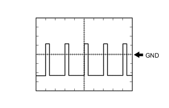
Waveform 1 (Charge voltage judgment and allowable amperage recognition signals)
Item Content Terminal N74-5 (CPLT) - Body ground Equipment Setting 5 V/DIV., 500 μs/DIV. Condition Plug-in charging Tech Tips
The duty ratio will vary depending on allowable amperage input of the charging cable or charging station used.
-

Waveform 2 (CAN communication signal)
Item Content Terminal CH1: N74-17 (CA4H) - Body ground
CH2: N74-16 (CA4L) - Body ground
Equipment Setting 1 V/DIV., 50 μs/DIV. Condition Power switch on (IG) Tech Tips
The waveform will vary depending on the content of the digital communication (digital signal).
-
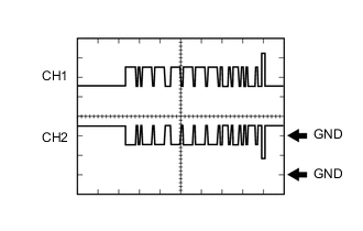
Waveform 3 (CAN communication signal)
Item Content Terminal CH1: N74-20 (CA1H) - Body ground
CH2: N74-19 (CA1L) - Body ground
Equipment Setting 1 V/DIV., 50 μs/DIV. Condition Power switch on (IG) Tech Tips
The waveform will vary depending on the content of the digital communication (digital signal).
-
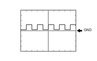
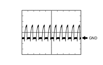
Waveform 4 (Charger cooling blower speed signal)
Item Content Terminal N74-33 (FTLS) - Body ground Equipment Setting 1 V/DIV., 5 ms/DIV. Condition Charger cooling blower operating Tech Tips
The wavelength will vary with the operating speed of the cooling fan.
-
Waveform 5 (Charger cooling blower operation signal)
Item Content Terminal N74-34 (FCTL) - Body ground Equipment Setting 1 V/DIV., 50 μs/DIV. Condition Charger cooling blower operating Tech Tips
The waveform will vary depending on the content of the digital communication (digital signal).
-
-