HYBRID BATTERY SYSTEM, Diagnostic DTC:P33EC16, P33ED16, P33EE16, P33EF16, P33F016
| DTC Code | DTC Name |
|---|---|
| P33EC16 | (Extreme) Hybrid/EV Battery Stack 1 Cell Circuit Voltage Below Threshold |
| P33ED16 | (Extreme) Hybrid/EV Battery Stack 2 Cell Circuit Voltage Below Threshold |
| P33EE16 | (Extreme) Hybrid/EV Battery Stack 3 Cell Circuit Voltage Below Threshold |
| P33EF16 | (Extreme) Hybrid/EV Battery Stack 4 Cell Circuit Voltage Below Threshold |
| P33F016 | (Extreme) Hybrid/EV Battery Stack 5 Cell Circuit Voltage Below Threshold |
DESCRIPTION
If the voltage of an HV battery cell is lower than the threshold for a certain amount of time, the battery ECU assembly will interpret this as a malfunction.
| DTC No. | Detection Item | DTC Detection Condition | Trouble Area | MIL | Warning Indicate |
|---|---|---|---|---|---|
| P33EC16 | (Extreme) Hybrid/EV Battery Stack 1 Cell Circuit Voltage Below Threshold | The voltage of any cell of the No. 1 HV supply stack sub-assembly has decreased excessively. (1 trip detection logic) |
|
Comes on | Master Warning Light: Comes on |
| P33ED16 | (Extreme) Hybrid/EV Battery Stack 2 Cell Circuit Voltage Below Threshold | The voltage of any cell of the No. 2 HV supply stack sub-assembly has decreased excessively. (1 trip detection logic) |
|
Comes on | Master Warning Light: Comes on |
| P33EE16 | (Extreme) Hybrid/EV Battery Stack 3 Cell Circuit Voltage Below Threshold | The voltage of any cell of the No. 3 HV supply stack sub-assembly has decreased excessively. (1 trip detection logic) |
|
Comes on | Master Warning Light: Comes on |
| P33EF16 | (Extreme) Hybrid/EV Battery Stack 4 Cell Circuit Voltage Below Threshold | The voltage of any cell of the No. 4 HV supply stack sub-assembly has decreased excessively. (1 trip detection logic) |
|
Comes on | Master Warning Light: Comes on |
| P33F016 | (Extreme) Hybrid/EV Battery Stack 5 Cell Circuit Voltage Below Threshold | The voltage of any cell of the No. 5 HV supply stack sub-assembly has decreased excessively. (1 trip detection logic) |
|
Comes on | Master Warning Light: Comes on |
CONFIRMATION DRIVING PATTERN
Tech Tips
After repair has been completed, clear the DTC and then check that the vehicle has returned to normal by performing the following All Readiness check procedure.
-
Connect the GTS to the DLC3.
-
Turn the power switch on (IG) and turn the GTS on.
-
Clear the DTCs (even if no DTCs are stored, perform the clear DTC procedure).
-
Turn the power switch off and wait for 2 minutes or more.
-
Turn the power switch on (IG) and turn the GTS on.
-
Drive the vehicle on urban roads for approximately 10 minutes.
-
Enter the following menus: Powertrain / HV Battery / Utility / All Readiness.
-
Check the DTC judgment result.
Tech Tips
-
If the judgment result shows NORMAL, the system is normal.
-
If the judgment result shows ABNORMAL, the system has a malfunction.
-
If the judgment result shows INCOMPLETE or N/A, perform driving pattern again.
-
CAUTION / NOTICE / HINT
CAUTION:
-

Before the following operations are conducted, take precautions to prevent electric shock by turning the power switch off, wearing insulated gloves, and removing the service plug grip from HV battery.
-
Inspecting the high-voltage system
-
Disconnecting the low voltage connector of the inverter with converter assembly
-
Disconnecting the low voltage connector of the HV battery
-
Disconnecting the low voltage connector of the electric vehicle charger assembly
-
Disconnecting the low voltage connector of the solar energy control unit
-

To prevent electric shock, make sure to remove the service plug grip to cut off the high voltage circuit before servicing the vehicle.
-

After removing the service plug grip from the HV battery, put it in your pocket to prevent other technicians from accidentally reconnecting it while you are working on the high-voltage system.
-
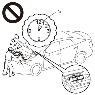
*a Without waiting for 10 minutes After removing the service plug grip, wait for at least 10 minutes before touching any of the high-voltage connectors or terminals. After waiting for 10 minutes, check the voltage at the terminals in the inspection point in the inverter with converter assembly. The voltage should be 0 V before beginning work.
Tech Tips
Waiting for at least 10 minutes is required to discharge the high-voltage capacitor inside the inverter with converter assembly and the electric vehicle charger assembly.
-
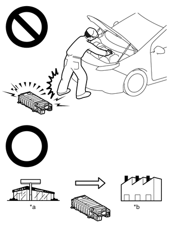
*a Dealer *b Battery Collection Agent When disposing of an HV battery, make sure to return it through an authorized collection agent who is capable of handling it safely. If the HV battery is returned via the manufacturer specified route, it will be returned properly and in a safe manner by an authorized collection agent.
-
Accidents such as electric shock may result if the HV battery is disposed of improperly or abandoned. Therefore, make sure to return all HV batteries through an authorized collection agent.
-
Before returning the HV battery, make sure to perform a recovery inspection.
-
Before returning the HV supply stack sub-assembly, make sure to perform a recovery inspection.
-
Make a note of the output DTCs as some of them may be necessary for recovery inspection of the HV battery and HV supply stack sub-assemblies.
-
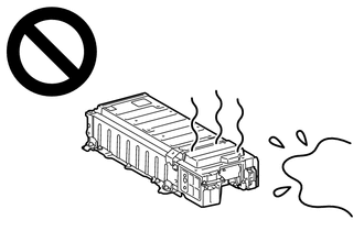
After removing the HV battery, keep it away from water. Exposure to water may cause the HV battery to produce heat, resulting in a fire.
Note
After turning the power switch off, waiting time may be required before disconnecting the cable from the negative (-) auxiliary battery terminal. Therefore, make sure to read the disconnecting the cable from the negative (-) auxiliary battery terminal notices before proceeding with work.
PROCEDURE
-
CHECK DTC OUTPUT (HV BATTERY, HYBRID CONTROL)
-
Connect the GTS to the DLC3.
-
Turn the power switch on (IG).
-
Enter the following menus: Powertrain / HV Battery and Hybrid Control / Trouble Codes.
-
Check for DTCs.
Powertrain > HV Battery > Trouble Codes
Powertrain > Hybrid Control > Trouble CodesResult Result Proceed to "P33EC16, P33ED16, P33EE16,P33EF16 or P33F016" only is output, or DTCs except the ones in the table below are also output. A DTCs of hybrid battery system in the table below are output. B DTCs of hybrid control system in the table below are output. C System Relevant DTC Hybrid battery system P060A47 Hybrid/EV Battery Energy Control Module Monitoring Processor Watchdog / Safety MCU Failure P060B49 Hybrid/EV Battery Energy Control Module A/D Processing Internal Electronic Failure P060687 Hybrid/EV Battery Energy Control Module Processor to Monitoring Processor Missing Message P1AC413 Hybrid/EV Battery Stack 1 Current Interrupt Device Circuit Open P1AC513 Hybrid/EV Battery Stack 2 Current Interrupt Device Circuit Open P1AC613 Hybrid/EV Battery Stack 3 Current Interrupt Device Circuit Open P1AC713 Hybrid/EV Battery Stack 4 Current Interrupt Device Circuit Open P1AC813 Hybrid/EV Battery Stack 5 Current Interrupt Device Circuit Open P1AC49E Hybrid/EV Battery Stack 1 Current Interrupt Device Stuck On P1AC59E Hybrid/EV Battery Stack 2 Current Interrupt Device Stuck On P1AC69E Hybrid/EV Battery Stack 3 Current Interrupt Device Stuck On P1AC79E Hybrid/EV Battery Stack 4 Current Interrupt Device Stuck On P1AC89E Hybrid/EV Battery Stack 5 Current Interrupt Device Stuck On Hybrid control system P0A1F94 Hybrid/EV Battery Energy Control Module Unexpected Operation -
Turn the power switch off.
B 
GO TO DTC CHART (HYBRID BATTERY SYSTEM) Click here
C
GO TO DTC CHART (HYBRID CONTROL SYSTEM) Click here
A 
-
-
CHECK DTC
-
Check the DTCs that were output when the vehicle was brought to the workshop.
Result Result Proceed to "P33EC16" is also output. A "P33ED16" is also output. B "P33EE16" is also output. C "P33EF16" is also output. D "P33F016" is also output. E
B 
CHECK CONNECTOR CONNECTION CONDITION (BATTERY ECU ASSEMBLY CONNECTOR) Click here
C
CHECK CONNECTOR CONNECTION CONDITION (BATTERY ECU ASSEMBLY CONNECTOR) Click here
D
CHECK CONNECTOR CONNECTION CONDITION (BATTERY ECU ASSEMBLY CONNECTOR) Click here
E
CHECK CONNECTOR CONNECTION CONDITION (BATTERY ECU ASSEMBLY CONNECTOR) Click here
A
-
-
CHECK CONNECTOR CONNECTION CONDITION (BATTERY ECU ASSEMBLY CONNECTOR)
CAUTION:
Be sure to wear insulated gloves and protective goggles.
-
Check that the service plug grip is not installed.
Note
After removing the service plug grip, do not turn the power switch on (READY), unless instructed by the repair manual because this may cause a malfunction.
-
Remove the upper hybrid battery cover sub-assembly.
-
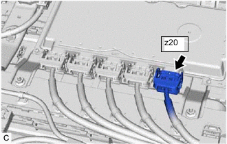
Check the connections of the z20 battery ECU assembly connector.
OK The connector is connected securely and there are no contact problems. -
Install the upper hybrid battery cover sub-assembly.
Result Result Proceed to OK A Not connected securely The terminals are not damaged or corroded B Not connected securely The terminals are damaged or corroded C
B
CONNECT SECURELY
C
REPLACE NO. 1 HV SUPPLY STACK SUB-ASSEMBLY Click here
A
-
-
CHECK FREEZE FRAME DATA
-
Connect the GTS to the DLC3.
-
Turn the power switch on (IG).
-
Enter the following menus: Powertrain / HV battery / Trouble Codes.
-
Read the value of freeze frame data items "Hybrid Battery Cell 1 voltage" through "Hybrid Battery Cell 19 voltage" for DTC P33EC16 and make a note if the value of any is 1.2 V or less.
Powertrain > HV Battery > Trouble Codes -
Turn the power switch off.
Result Proceed to NEXT
NEXT
-
-
CHECK NO. 1 HV SUPPLY STACK SUB-ASSEMBLY (HYBRID BATTERY CELL VOLTAGE)
CAUTION:
-
Be sure to wear insulated gloves and protective goggles.
-
Disconnect only the connector corresponding to the HV battery cell to be checked. Do not disconnect the other connectors.
Note
Make sure to use tester probes with a diameter of approximately 0.5 mm (0.0197 in.) when measuring the voltage of each HV battery cell.
-
Check that the service plug grip is not installed.
Note
After removing the service plug grip, do not turn the power switch on (READY), unless instructed by the repair manual because this may cause a malfunction.
-
Remove the upper hybrid battery cover sub-assembly.
-
Disconnect the z20 battery ECU assembly connector.
Note
-
Before disconnecting the connector, check that it is not loose or disconnected.
-
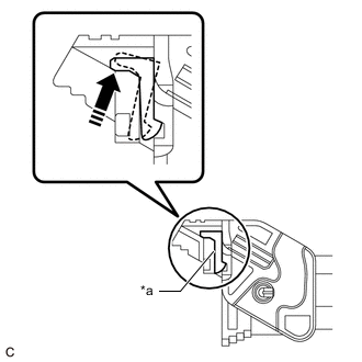
*a Lever Lock Make sure to release the lock of the lock lever before moving it.
-
If the connector cannot be disconnected, check if the lock lever is completely unlocked.
-
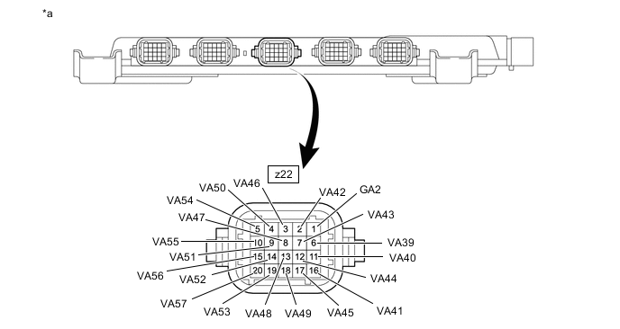
-
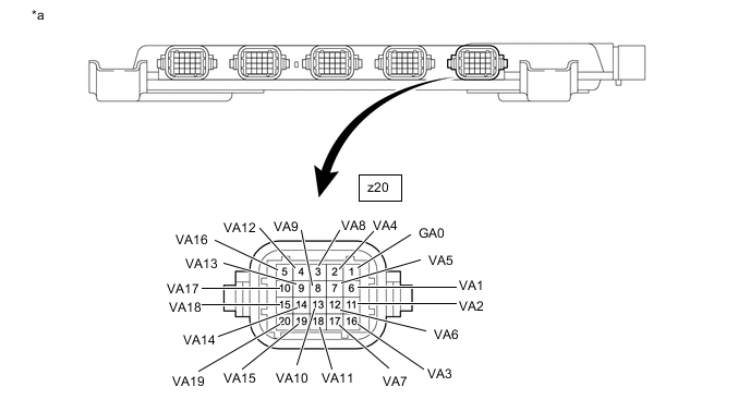
*a Front view of wire harness connector
(to Battery ECU Assembly)
Measure the voltage according to the value(s) in the table below.
Tech Tips
Measure the voltage of the HV battery cells whose value in the freeze frame data was 1.2 V or less only.
Hybrid Battery Cell Tester Connection Condition 1 z20-1 (GA0) - z20-6 (VA1) Always 2 z20-6 (VA1) - z20-11 (VA2) Always 3 z20-11 (VA2) - z20-16 (VA3) Always 4 z20-16 (VA3) - z20-2 (VA4) Always 5 z20-2 (VA4) - z20-7 (VA5) Always 6 z20-7 (VA5) - z20-12 (VA6) Always 7 z20-12 (VA6) - z20-17 (VA7) Always 8 z20-17 (VA7) - z20-3 (VA8) Always 9 z20-3 (VA8) - z20-8 (VA9) Always 10 z20-8 (VA9) - z20-13 (VA10) Always 11 z20-13 (VA10) - z20-18 (VA11) Always 12 z20-18 (VA11) - z20-4 (VA12) Always 13 z20-4 (VA12) - z20-9 (VA13) Always 14 z20-9 (VA13) - z20-14 (VA14) Always 15 z20-14 (VA14) - z20-19 (VA15) Always 16 z20-19 (VA15) - z20-5 (VA16) Always 17 z20-5 (VA16) - z20-10 (VA17) Always 18 z20-10 (VA17) - z20-15 (VA18) Always 19 z20-15 (VA18) - z20-20 (VA19) Always CAUTION:
Make sure not to cross the electrodes of an electrical tester measurement terminals.
Note
Make sure to check the polarity of each terminal (positive (+) or negative (-)) before connecting a tester.
Result Result Proceed to The voltage between the terminals is 1.2 V or less. A Other than above B -
Reconnect the z20 battery ECU assembly connector.
-
Install the upper hybrid battery cover sub-assembly.
B
REPLACE BATTERY ECU ASSEMBLY Click here
A
-
-
CHECK BATTERY ECU ASSEMBLY (VA1 - VA19)
Note
Make sure to use tester probes with a diameter of approximately 0.5 mm (0.0197 in.) when measuring the resistance.
-
Remove the battery ECU assembly.
-
Measure the resistance according to the value(s) in the table below.
Tech Tips
Only inspect the terminals of the battery ECU assembly which correspond to the HV battery cells which measured 1.2 V or less in the previous step.
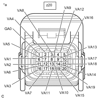
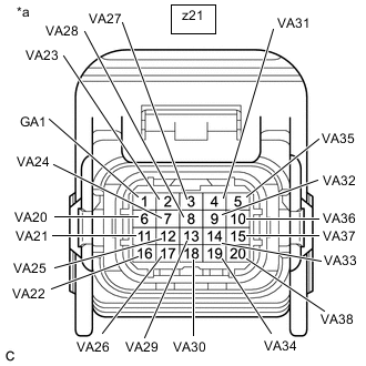
*a Component without harness connected
(Battery ECU Assembly)
- - Standard Resistance Hybrid Battery Cell Tester Connection
(Tester Probe Polarity)
Condition Specified Condition 1 z20-1 (GA0) (-) - z20-6 (VA1) (+) Always 50 kΩ or more 2 z20-6 (VA1) (-) - z20-11 (VA2) (+) Always 50 kΩ or more 3 z20-11 (VA2) (-) - z20-16 (VA3) (+) Always 50 kΩ or more 4 z20-16 (VA3) (-) - z20-2 (VA4) (+) Always 50 kΩ or more 5 z20-2 (VA4) (-) - z20-7 (VA5) (+) Always 50 kΩ or more 6 z20-7 (VA5) (-) - z20-12 (VA6) (+) Always 50 kΩ or more 7 z20-12 (VA6) (-) - z20-17 (VA7) (+) Always 50 kΩ or more 8 z20-17 (VA7) (-) - z20-3 (VA8) (+) Always 50 kΩ or more 9 z20-3 (VA8) (-) - z20-8 (VA9) (+) Always 50 kΩ or more 10 z20-8 (VA9) (-) - z20-13 (VA10) (+) Always 50 kΩ or more 11 z20-13 (VA10) (-) - z20-18 (VA11) (+) Always 50 kΩ or more 12 z20-18 (VA11) (-) - z20-4 (VA12) (+) Always 50 kΩ or more 13 z20-4 (VA12) (-) - z20-9 (VA13) (+) Always 50 kΩ or more 14 z20-9 (VA13) (-) - z20-14 (VA14) (+) Always 50 kΩ or more 15 z20-14 (VA14) (-) - z20-19 (VA15) (+) Always 50 kΩ or more 16 z20-19 (VA15) (-) - z20-5 (VA16) (+) Always 50 kΩ or more 17 z20-5 (VA16) (-) - z20-10 (VA17) (+) Always 50 kΩ or more 18 z20-10 (VA17) (-) - z20-15 (VA18) (+) Always 50 kΩ or more 19 z20-15 (VA18) (-) - z20-20 (VA19) (+) Always 50 kΩ or more Note
-
Make sure to check the polarity of each terminal (positive (+) or negative (-)) before connecting a tester.
-
Read the resistance after the value has stabilized.
-
In order to avoid damaging the terminals of the battery ECU assembly, make sure to use tester probes with a diameter of approximately 0.5 mm (0.0197 in.) when measuring the resistance of the battery ECU assembly.
-
-
Install the battery ECU assembly.
Result Result Proceed to The resistance between the terminals is 50 kΩ or more. A Other than above B
A
REPLACE NO. 1 HV SUPPLY STACK SUB-ASSEMBLY Click here
B
-
-
REPLACE NO. 1 HV SUPPLY STACK SUB-ASSEMBLY
Result Proceed to NEXT
NEXT
REPLACE BATTERY ECU ASSEMBLY Click here
-
CHECK CONNECTOR CONNECTION CONDITION (BATTERY ECU ASSEMBLY CONNECTOR)
CAUTION:
Be sure to wear insulated gloves and protective goggles.
-
Check that the service plug grip is not installed.
Note
After removing the service plug grip, do not turn the power switch on (READY), unless instructed by the repair manual because this may cause a malfunction.
-
Remove the upper hybrid battery cover sub-assembly.
-
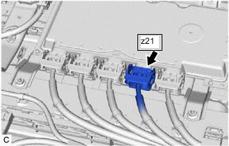
Check the connections of the z21 battery ECU assembly connector.
OK The connector is connected securely and there are no contact problems. -
Install the upper hybrid battery cover sub-assembly.
Result Result Proceed to OK A Not connected securely The terminals are not damaged or corroded B Not connected securely The terminals are damaged or corroded C
B
CONNECT SECURELY
C
REPLACE NO. 2 HV SUPPLY STACK SUB-ASSEMBLY Click here
A
-
-
CHECK FREEZE FRAME DATA
-
Connect the GTS to the DLC3.
-
Turn the power switch on (IG).
-
Enter the following menus: Powertrain / HV battery / Trouble Codes.
-
Read the value of freeze frame data items "Hybrid Battery Cell 20 voltage" through "Hybrid Battery Cell 38 voltage" for DTC P33ED16 and make a note if the value of any is 1.2 V or less.
Powertrain > HV Battery > Trouble Codes -
Turn the power switch off.
Result Proceed to NEXT
NEXT
-
-
CHECK NO. 2 HV SUPPLY STACK SUB-ASSEMBLY (HYBRID BATTERY CELL VOLTAGE)
CAUTION:
-
Be sure to wear insulated gloves and protective goggles.
-
Disconnect only the connector corresponding to the HV battery cell to be checked. Do not disconnect the other connectors.
Note
Make sure to use tester probes with a diameter of approximately 0.5 mm (0.0197 in.) when measuring the voltage of each HV battery cell.
-
Check that the service plug grip is not installed.
Note
After removing the service plug grip, do not turn the power switch on (READY), unless instructed by the repair manual because this may cause a malfunction.
-
Remove the upper hybrid battery cover sub-assembly.
-
Disconnect the z21 battery ECU assembly connector.
Note
-
Before disconnecting the connector, check that it is not loose or disconnected.
-
*a Lever Lock Make sure to release the lock of the lock lever before moving it.
-
If the connector cannot be disconnected, check if the lock lever is completely unlocked.
-
-
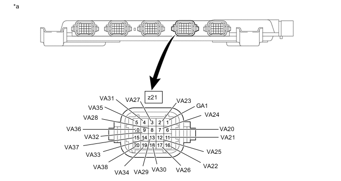
*a Front view of wire harness connector
(to Battery ECU Assembly)
Measure the voltage according to the value(s) in the table below.
Tech Tips
Measure the voltage of the HV battery cells whose value in the freeze frame data was 1.2 V or less only.
Hybrid Battery Cell Tester Connection Condition 20 z21-1 (GA1) - z21-6 (VA20) Always 21 z21-6 (VA20) - z21-11 (VA21) Always 22 z21-11 (VA21) - z21-16 (VA22) Always 23 z21-16 (VA22) - z21-2 (VA23) Always 24 z21-2 (VA23) - z21-7 (VA24) Always 25 z21-7 (VA24) - z21-12 (VA25) Always 26 z21-12 (VA25) - z21-17 (VA26) Always 27 z21-17 (VA26) - z21-3 (VA27) Always 28 z21-3 (VA27) - z21-8 (VA28) Always 29 z21-8 (VA28) - z21-13 (VA29) Always 30 z21-13 (VA29) - z21-18 (VA30) Always 31 z21-18 (VA30) - z21-4 (VA31) Always 32 z21-4 (VA31) - z21-9 (VA32) Always 33 z21-9 (VA32) - z21-14 (VA33) Always 34 z21-14 (VA33) - z21-19 (VA34) Always 35 z21-19 (VA34) - z21-5 (VA35) Always 36 z21-5 (VA35) - z21-10 (VA36) Always 37 z21-10 (VA36) - z21-15 (VA37) Always 38 z21-15 (VA37) - z21-20 (VA38) Always CAUTION:
Make sure not to cross the electrodes of an electrical tester measurement terminals.
Note
Make sure to check the polarity of each terminal (positive (+) or negative (-)) before connecting a tester.
Result Result Proceed to The voltage between the terminals is 1.2 V or less. A Other than above B -
Reconnect the z21 battery ECU assembly connector.
-
Install the upper hybrid battery cover sub-assembly.
B
REPLACE BATTERY ECU ASSEMBLY Click here
A
-
-
CHECK BATTERY ECU ASSEMBLY (VA20 - VA38)
Note
Make sure to use tester probes with a diameter of approximately 0.5 mm (0.0197 in.) when measuring the resistance.
-
Remove the battery ECU assembly.
-
Measure the resistance according to the value(s) in the table below.
Tech Tips
Only inspect the terminals of the battery ECU assembly which correspond to the HV battery cells which measured 1.2 V or less in the previous step.
*a Component without harness connected
(Battery ECU Assembly)
- - Standard Resistance Hybrid Battery Cell Tester Connection
(Tester Probe Polarity)
Condition Specified Condition 20 z21-1 (GA1) (-) - z21-6 (VA20) (+) Always 50 kΩ or more 21 z21-6 (VA20) (-) - z21-11 (VA21) (+) Always 50 kΩ or more 22 z21-11 (VA21) (-) - z21-16 (VA22) (+) Always 50 kΩ or more 23 z21-16 (VA22) (-) - z21-2 (VA23) (+) Always 50 kΩ or more 24 z21-2 (VA23) (-) - z21-7 (VA24) (+) Always 50 kΩ or more 25 z21-7 (VA24) (-) - z21-12 (VA25) (+) Always 50 kΩ or more 26 z21-12 (VA25) (-) - z21-17 (VA26) (+) Always 50 kΩ or more 27 z21-17 (VA26) (-) - z21-3 (VA27) (+) Always 50 kΩ or more 28 z21-3 (VA27) (-) - z21-8 (VA28) (+) Always 50 kΩ or more 29 z21-8 (VA28) (-) - z21-13 (VA29) (+) Always 50 kΩ or more 30 z21-13 (VA29) (-) - z21-18 (VA30) (+) Always 50 kΩ or more 31 z21-18 (VA30) (-) - z21-4 (VA31) (+) Always 50 kΩ or more 32 z21-4 (VA31) (-) - z21-9 (VA32) (+) Always 50 kΩ or more 33 z21-9 (VA32) (-) - z21-14 (VA33) (+) Always 50 kΩ or more 34 z21-14 (VA33) (-) - z21-19 (VA34) (+) Always 50 kΩ or more 35 z21-19 (VA34) (-) - z21-5 (VA35) (+) Always 50 kΩ or more 36 z21-5 (VA35) (-) - z21-10 (VA36) (+) Always 50 kΩ or more 37 z21-10 (VA36) (-) - z21-15 (VA37) (+) Always 50 kΩ or more 38 z21-15 (VA37) (-) - z21-20 (VA38) (+) Always 50 kΩ or more Note
-
Make sure to check the polarity of each terminal (positive (+) or negative (-)) before connecting a tester.
-
Read the resistance after the value has stabilized.
-
In order to avoid damaging the terminals of the battery ECU assembly, make sure to use tester probes with a diameter of approximately 0.5 mm (0.0197 in.) when measuring the resistance of the battery ECU assembly.
-
-
Install the battery ECU assembly.
Result Result Proceed to The resistance between the terminals is 50 kΩ or more. A Other than above B
A
REPLACE NO. 2 HV SUPPLY STACK SUB-ASSEMBLY Click here
B
-
-
REPLACE NO. 2 HV SUPPLY STACK SUB-ASSEMBLY
Result Proceed to NEXT
NEXT
REPLACE BATTERY ECU ASSEMBLY Click here
-
CHECK CONNECTOR CONNECTION CONDITION (BATTERY ECU ASSEMBLY CONNECTOR)
CAUTION:
Be sure to wear insulated gloves and protective goggles.
-
Check that the service plug grip is not installed.
Note
After removing the service plug grip, do not turn the power switch on (READY), unless instructed by the repair manual because this may cause a malfunction.
-
Remove the upper hybrid battery cover sub-assembly.
-
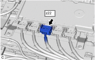
Check the connections of the z22 battery ECU assembly connector.
OK The connector is connected securely and there are no contact problems. -
Install the upper hybrid battery cover sub-assembly.
Result Result Proceed to OK A Not connected securely The terminals are not damaged or corroded B Not connected securely The terminals are damaged or corroded C
B
CONNECT SECURELY
C
REPLACE NO. 3 HV SUPPLY STACK SUB-ASSEMBLY Click here
A
-
-
CHECK FREEZE FRAME DATA
-
Connect the GTS to the DLC3.
-
Turn the power switch on (IG).
-
Enter the following menus: Powertrain / HV battery / Trouble Codes.
-
Read the value of freeze frame data items "Hybrid Battery Cell 39 voltage" through "Hybrid Battery Cell 57 voltage" for DTC P33EE16 and make a note if the value of any is 1.2 V or less.
Powertrain > HV Battery > Trouble Codes -
Turn the power switch off.
Result Proceed to NEXT
NEXT
-
-
CHECK NO. 3 HV SUPPLY STACK SUB-ASSEMBLY (HYBRID BATTERY CELL VOLTAGE)
CAUTION:
-
Be sure to wear insulated gloves and protective goggles.
-
Disconnect only the connector corresponding to the HV battery cell to be checked. Do not disconnect the other connectors.
Note
Make sure to use tester probes with a diameter of approximately 0.5 mm (0.0197 in.) when measuring the voltage of each HV battery cell.
-
Check that the service plug grip is not installed.
Note
After removing the service plug grip, do not turn the power switch on (READY), unless instructed by the repair manual because this may cause a malfunction.
-
Remove the upper hybrid battery cover sub-assembly.
-
Disconnect the z22 battery ECU assembly connector.
Note
-
Before disconnecting the connector, check that it is not loose or disconnected.
-
*a Lever Lock Make sure to release the lock of the lock lever before moving it.
-
If the connector cannot be disconnected, check if the lock lever is completely unlocked.
-
-
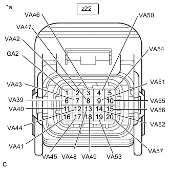
*a Front view of wire harness connector
(to Battery ECU Assembly)
Measure the voltage according to the value(s) in the table below.
Tech Tips
Measure the voltage of the HV battery cells whose value in the freeze frame data was 1.2 V or less only.
Hybrid Battery Cell Tester Connection Condition 39 z22-1 (GA2) - z22-6 (VA39) Always 40 z22-6 (VA39) - z22-11 (VA40) Always 41 z22-11 (VA40) - z22-16 (VA41) Always 42 z22-16 (VA41) - z22-2 (VA42) Always 43 z22-2 (VA42) - z22-7 (VA43) Always 44 z22-7 (VA43) - z22-12 (VA44) Always 45 z22-12 (VA44) - z22-17 (VA45) Always 46 z22-17 (VA45) - z22-3 (VA46) Always 47 z22-3 (VA46) - z22-8 (VA47) Always 48 z22-8 (VA47) - z22-13 (VA48) Always 49 z22-13 (VA48) - z22-18 (VA49) Always 50 z22-18 (VA49) - z22-4 (VA50) Always 51 z22-4 (VA50) - z22-9 (VA51) Always 52 z22-9 (VA51) - z22-14 (VA52) Always 53 z22-14 (VA52) - z22-19 (VA53) Always 54 z22-19 (VA53) - z22-5 (VA54) Always 55 z22-5 (VA54) - z22-10 (VA55) Always 56 z22-10 (VA55) - z22-15 (VA56) Always 57 z22-15 (VA56) - z22-20 (VA57) Always CAUTION:
Make sure not to cross the electrodes of an electrical tester measurement terminals.
Note
Make sure to check the polarity of each terminal (positive (+) or negative (-)) before connecting a tester.
Result Result Proceed to The voltage between the terminals is 1.2 V or less. A Other than above B -
Reconnect the z22 battery ECU assembly connector.
-
Install the upper hybrid battery cover sub-assembly.
B
REPLACE BATTERY ECU ASSEMBLY Click here
A
-
-
CHECK BATTERY ECU ASSEMBLY (VA39 - VA57)
Note
Make sure to use tester probes with a diameter of approximately 0.5 mm (0.0197 in.) when measuring the resistance.
-
Remove the battery ECU assembly.
-
Measure the resistance according to the value(s) in the table below.
Tech Tips
Only inspect the terminals of the battery ECU assembly which correspond to the HV battery cells which measured 1.2 V or less in the previous step.
*a Component without harness connected
(Battery ECU Assembly)
- - Standard Resistance Hybrid Battery Cell Tester Connection
(Tester Probe Polarity)
Condition Specified Condition 39 z22-1 (GA2) (-) - z22-6 (VA39) (+) Always 50 kΩ or more 40 z22-6 (VA39) (-) - z22-11 (VA40) (+) Always 50 kΩ or more 41 z22-11 (VA40) (-) - z22-16 (VA41) (+) Always 50 kΩ or more 42 z22-16 (VA41) (-) - z22-2 (VA42) (+) Always 50 kΩ or more 43 z22-2 (VA42) (-) - z22-7 (VA43) (+) Always 50 kΩ or more 44 z22-7 (VA43) (-) - z22-12 (VA44) (+) Always 50 kΩ or more 45 z22-12 (VA44) (-) - z22-17 (VA45) (+) Always 50 kΩ or more 46 z22-17 (VA45) (-) - z22-3 (VA46) (+) Always 50 kΩ or more 47 z22-3 (VA46) (-) - z22-8 (VA47) (+) Always 50 kΩ or more 48 z22-8 (VA47) (-) - z22-13 (VA48) (+) Always 50 kΩ or more 49 z22-13 (VA48) (-) - z22-18 (VA49) (+) Always 50 kΩ or more 50 z22-18 (VA49) (-) -z22-4 (VA50) (+) Always 50 kΩ or more 51 z22-4 (VA50) (-) - z22-9 (VA51) (+) Always 50 kΩ or more 52 z22-9 (VA51) (-) - z22-14 (VA52) (+) Always 50 kΩ or more 53 z22-14 (VA52) (-) - z22-19 (VA53) (+) Always 50 kΩ or more 54 z22-19 (VA53) (-) - z22-5 (VA54) (+) Always 50 kΩ or more 55 z22-5 (VA54) (-) - z22-10 (VA55) (+) Always 50 kΩ or more 56 z22-10 (VA55) (-) - z22-15 (VA56) (+) Always 50 kΩ or more 57 z22-15 (VA56) (-) - z22-20 (VA57) (+) Always 50 kΩ or more Note
-
Make sure to check the polarity of each terminal (positive (+) or negative (-)) before connecting a tester.
-
Read the resistance after the value has stabilized.
-
In order to avoid damaging the terminals of the battery ECU assembly, make sure to use tester probes with a diameter of approximately 0.5 mm (0.0197 in.) when measuring the resistance of the battery ECU assembly.
-
-
Install the battery ECU assembly.
Result Result Proceed to The resistance between the terminals is 50 kΩ or more. A Other than above B
A
REPLACE NO. 3 HV SUPPLY STACK SUB-ASSEMBLY Click here
B
-
-
REPLACE NO. 3 HV SUPPLY STACK SUB-ASSEMBLY
Result Proceed to NEXT
NEXT
REPLACE BATTERY ECU ASSEMBLY Click here
-
CHECK CONNECTOR CONNECTION CONDITION (BATTERY ECU ASSEMBLY CONNECTOR)
CAUTION:
Be sure to wear insulated gloves and protective goggles.
-
Check that the service plug grip is not installed.
Note
After removing the service plug grip, do not turn the power switch on (READY), unless instructed by the repair manual because this may cause a malfunction.
-
Remove the upper hybrid battery cover sub-assembly.
-
Check the connections of the z23 battery ECU assembly connector.
OK The connector is connected securely and there are no contact problems. -
Install the upper hybrid battery cover sub-assembly.
Result Result Proceed to OK A Not connected securely The terminals are not damaged or corroded B Not connected securely The terminals are damaged or corroded C
B
CONNECT SECURELY
C
REPLACE NO. 4 HV SUPPLY STACK SUB-ASSEMBLY Click here
A
-
-
CHECK FREEZE FRAME DATA
-
Connect the GTS to the DLC3.
-
Turn the power switch on (IG).
-
Enter the following menus: Powertrain / HV battery / Trouble Codes.
-
Read the value of freeze frame data items "Hybrid Battery Cell 58 voltage" through "Hybrid Battery Cell 76 voltage" for DTC P33EF16 and make a note if the value of any is 1.2 V or less.
Powertrain > HV Battery > Trouble Codes -
Turn the power switch off.
Result Proceed to NEXT
NEXT
-
-
CHECK NO. 4 HV SUPPLY STACK SUB-ASSEMBLY (HYBRID BATTERY CELL VOLTAGE)
CAUTION:
-
Be sure to wear insulated gloves and protective goggles.
-
Disconnect only the connector corresponding to the HV battery cell to be checked. Do not disconnect the other connectors.
Note
Make sure to use tester probes with a diameter of approximately 0.5 mm (0.0197 in.) when measuring the voltage of each HV battery cell.
-
Check that the service plug grip is not installed.
Note
After removing the service plug grip, do not turn the power switch on (READY), unless instructed by the repair manual because this may cause a malfunction.
-
Remove the upper hybrid battery cover sub-assembly.
-
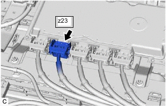
Disconnect the z23 battery ECU assembly connector.
Note
-
Before disconnecting the connector, check that it is not loose or disconnected.
-
*a Lever Lock Make sure to release the lock of the lock lever before moving it.
-
If the connector cannot be disconnected, check if the lock lever is completely unlocked.
-
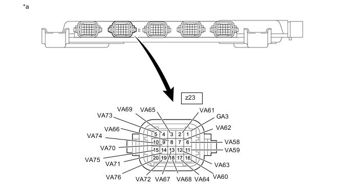
-
*a Front view of wire harness connector
(to Battery ECU Assembly)
Measure the voltage according to the value(s) in the table below.
Tech Tips
Measure the voltage of the HV battery cells whose value in the freeze frame data was 1.2 V or less only.
Hybrid Battery Cell Tester Connection Condition 58 z23-1 (GA3) - z23-6 (VA58) Always 59 z23-6 (VA58) - z23-11 (VA59) Always 60 z23-11 (VA59) - z23-16 (VA60) Always 61 z23-16 (VA60) - z23-2 (VA61) Always 62 z23-2 (VA61) - z23-7 (VA62) Always 63 z23-7 (VA62) - z23-12 (VA63) Always 64 z23-12 (VA63) - z23-17 (VA64) Always 65 z23-17 (VA64) - z23-3 (VA65) Always 66 z23-3 (VA65) - z23-8 (VA66) Always 67 z23-8 (VA66) - z23-13 (VA67) Always 68 z23-13 (VA67) - z23-18 (VA68) Always 69 z23-18 (VA68) - z23-4 (VA69) Always 70 z23-4 (VA69) - z23-9 (VA70) Always 71 z23-9 (VA70) - z23-14 (VA71) Always 72 z23-14 (VA71) - z23-19 (VA72) Always 73 z23-19 (VA72) - z23-5 (VA73) Always 74 z23-5 (VA73) - z23-10 (VA74) Always 75 z23-10 (VA74) - z23-15 (VA75) Always 76 z23-15 (VA75) - z23-20 (VA76) Always CAUTION:
Make sure not to cross the electrodes of an electrical tester measurement terminals.
Note
Make sure to check the polarity of each terminal (positive (+) or negative (-)) before connecting a tester.
Result Result Proceed to The voltage between the terminals is 1.2 V or less. A Other than above B -
Reconnect the z23 battery ECU assembly connector.
-
Install the upper hybrid battery cover sub-assembly.
B
REPLACE BATTERY ECU ASSEMBLY Click here
A
-
-
CHECK BATTERY ECU ASSEMBLY (VA58 - VA76)
Note
Make sure to use tester probes with a diameter of approximately 0.5 mm (0.0197 in.) when measuring the resistance.
-
Remove the battery ECU assembly.
-
Measure the resistance according to the value(s) in the table below.
Tech Tips
Only inspect the terminals of the battery ECU assembly which correspond to the HV battery cells which measured 1.2 V or less in the previous step.
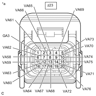
*a Component without harness connected
(Battery ECU Assembly)
- - Standard Resistance Hybrid Battery Cell Tester Connection
(Tester Probe Polarity)
Condition Specified Condition 58 z23-1 (GA3) (-) - z23-6 (VA58) (+) Always 50 kΩ or more 59 z23-6 (VA58) (-) - z23-11 (VA59) (+) Always 50 kΩ or more 60 z23-11 (VA59) (-) - z23-16 (VA60) (+) Always 50 kΩ or more 61 z23-16 (VA60) (-) - z23-2 (VA61) (+) Always 50 kΩ or more 62 z23-2 (VA61) (-) - z23-7 (VA62) (+) Always 50 kΩ or more 63 z23-7 (VA62) (-) - z23-12 (VA63) (+) Always 50 kΩ or more 64 z23-12 (VA63) (-) - z23-17 (VA64) (+) Always 50 kΩ or more 65 z23-17 (VA64) (-) - z23-3 (VA65) (+) Always 50 kΩ or more 66 z23-3 (VA65) (-) - z23-8 (VA66) (+) Always 50 kΩ or more 67 z23-8 (VA66) (-) - z23-13 (VA67) (+) Always 50 kΩ or more 68 z23-13 (VA67) (-) - z23-18 (VA68) (+) Always 50 kΩ or more 69 z23-18 (VA68) (-) -z23-4 (VA69) (+) Always 50 kΩ or more 70 z23-4 (VA69) (-) - z23-9 (VA70) (+) Always 50 kΩ or more 71 z23-9 (VA70) (-) - z23-14 (VA71) (+) Always 50 kΩ or more 72 z23-14 (VA71) (-) - z23-19 (VA72) (+) Always 50 kΩ or more 73 z23-19 (VA72) (-) - z23-5 (VA73) (+) Always 50 kΩ or more 74 z23-5 (VA73) (-) - z23-10 (VA74) (+) Always 50 kΩ or more 75 z23-10 (VA74) (-) - z23-15 (VA75) (+) Always 50 kΩ or more 76 z23-15 (VA75) (-) - z23-20 (VA76) (+) Always 50 kΩ or more Note
-
Make sure to check the polarity of each terminal (positive (+) or negative (-)) before connecting a tester.
-
Read the resistance after the value has stabilized.
-
In order to avoid damaging the terminals of the battery ECU assembly, make sure to use tester probes with a diameter of approximately 0.5 mm (0.0197 in.) when measuring the resistance of the battery ECU assembly.
-
-
Install the battery ECU assembly.
Result Result Proceed to The resistance between the terminals is 50 kΩ or more. A Other than above B
A
REPLACE NO. 4 HV SUPPLY STACK SUB-ASSEMBLY Click here
B
-
-
REPLACE NO. 4 HV SUPPLY STACK SUB-ASSEMBLY
Result Proceed to NEXT
NEXT
REPLACE BATTERY ECU ASSEMBLY Click here
-
CHECK CONNECTOR CONNECTION CONDITION (BATTERY ECU ASSEMBLY CONNECTOR)
CAUTION:
Be sure to wear insulated gloves and protective goggles.
-
Check that the service plug grip is not installed.
Note
After removing the service plug grip, do not turn the power switch on (READY), unless instructed by the repair manual because this may cause a malfunction.
-
Remove the upper hybrid battery cover sub-assembly.
-
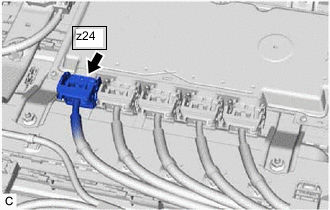
Check the connections of the z24 battery ECU assembly connector.
OK The connector is connected securely and there are no contact problems. -
Install the upper hybrid battery cover sub-assembly.
Result Result Proceed to OK A Not connected securely The terminals are not damaged or corroded B Not connected securely The terminals are damaged or corroded C
B
CONNECT SECURELY
C
REPLACE NO. 5 HV SUPPLY STACK SUB-ASSEMBLY Click here
A
-
-
CHECK FREEZE FRAME DATA
-
Connect the GTS to the DLC3.
-
Turn the power switch on (IG).
-
Enter the following menus: Powertrain / HV battery / Trouble Codes.
-
Read the value of freeze frame data items "Hybrid Battery Cell 77 voltage" through "Hybrid Battery Cell 95 voltage" for DTC P33F016 and make a note if the value of any is 1.2 V or less.
Powertrain > HV Battery > Trouble Codes -
Turn the power switch off.
Result Proceed to NEXT
NEXT
-
-
CHECK NO. 5 HV SUPPLY STACK SUB-ASSEMBLY (HYBRID BATTERY CELL VOLTAGE)
CAUTION:
-
Be sure to wear insulated gloves and protective goggles.
-
Disconnect only the connector corresponding to the HV battery cell to be checked. Do not disconnect the other connectors.
Note
Make sure to use tester probes with a diameter of approximately 0.5 mm (0.0197 in.) when measuring the voltage of each HV battery cell.
-
Check that the service plug grip is not installed.
Note
After removing the service plug grip, do not turn the power switch on (READY), unless instructed by the repair manual because this may cause a malfunction.
-
Remove the upper hybrid battery cover sub-assembly.
-
Disconnect the z24 battery ECU assembly connector.
Note
-
Before disconnecting the connector, check that it is not loose or disconnected.
-
*a Lever Lock Make sure to release the lock of the lock lever before moving it.
-
If the connector cannot be disconnected, check if the lock lever is completely unlocked.
-
-
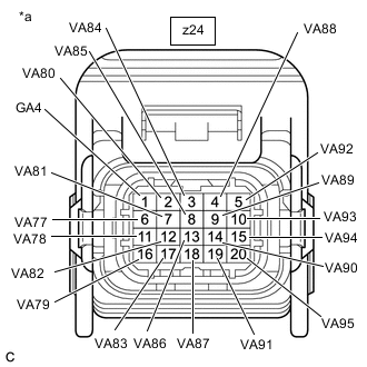
*a Front view of wire harness connector
(to Battery ECU Assembly)
Measure the voltage according to the value(s) in the table below.
Tech Tips
Measure the voltage of the HV battery cells whose value in the freeze frame data was 1.2 V or less only.
Hybrid Battery Cell Tester Connection Condition 77 z24-1 (GA4) - z24-6 (VA77) Always 78 z24-6 (VA77) - z24-11 (VA78) Always 79 z24-11 (VA78) - z24-16 (VA79) Always 80 z24-16 (VA79) - z24-2 (VA80) Always 81 z24-2 (VA80) - z24-7 (VA81) Always 82 z24-7 (VA81) - z24-12 (VA82) Always 83 z24-12 (VA82) - z24-17 (VA83) Always 84 z24-17 (VA83) - z24-3 (VA84) Always 85 z24-3 (VA84) - z24-8 (VA85) Always 86 z24-8 (VA85) - z24-13 (VA86) Always 87 z24-13 (VA86) - z24-18 (VA87) Always 88 z24-18 (VA87) - z24-4 (VA88) Always 89 z24-4 (VA88) - z24-9 (VA89) Always 90 z24-9 (VA89) - z24-14 (VA90) Always 91 z24-14 (VA90) - z24-19 (VA91) Always 92 z24-19 (VA91) - z24-5 (VA92) Always 93 z24-5 (VA92) - z24-10 (VA93) Always 94 z24-10 (VA93) - z24-15 (VA94) Always 95 z24-15 (VA94) - z24-20 (VA95) Always CAUTION:
Make sure not to cross the electrodes of an electrical tester measurement terminals.
Note
Make sure to check the polarity of each terminal (positive (+) or negative (-)) before connecting a tester.
Result Result Proceed to The voltage between the terminals is 1.2 V or less. A Other than above B -
Reconnect the z24 battery ECU assembly connector.
-
Install the upper hybrid battery cover sub-assembly.
B
REPLACE BATTERY ECU ASSEMBLY Click here
A
-
-
CHECK BATTERY ECU ASSEMBLY (VA77 - VA95)
Note
Make sure to use tester probes with a diameter of approximately 0.5 mm (0.0197 in.) when measuring the resistance.
-
Remove the battery ECU assembly.
-
Measure the resistance according to the value(s) in the table below.
Tech Tips
Only inspect the terminals of the battery ECU assembly which correspond to the HV battery cells which measured 1.2 V or less in the previous step.
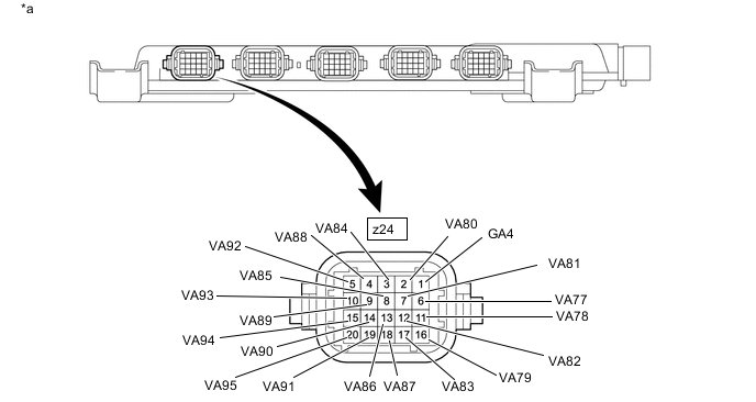
*a Component without harness connected
(Battery ECU Assembly)
- - Standard Resistance Hybrid Battery Cell Tester Connection
(Tester Probe Polarity)
Condition Specified Condition 77 z24-1 (GA4) (-) - z24-6 (VA77) (+) Always 50 kΩ or more 78 z24-6 (VA77) (-) - z24-11 (VA78) (+) Always 50 kΩ or more 79 z24-11 (VA78) (-) - z24-16 (VA79) (+) Always 50 kΩ or more 80 z24-16 (VA79) (-) - z24-2 (VA80) (+) Always 50 kΩ or more 81 z24-2 (VA80) (-) - z24-7 (VA81) (+) Always 50 kΩ or more 82 z24-7 (VA81) (-) - z24-12 (VA82) (+) Always 50 kΩ or more 83 z24-12 (VA82) (-) - z24-17 (VA83) (+) Always 50 kΩ or more 84 z24-17 (VA83) (-) - z24-3 (VA84) (+) Always 50 kΩ or more 85 z24-3 (VA84) (-) - z24-8 (VA85) (+) Always 50 kΩ or more 86 z24-8 (VA85) (-) - z24-13 (VA86) (+) Always 50 kΩ or more 87 z24-13 (VA86) (-) - z24-18 (VA87) (+) Always 50 kΩ or more 88 z24-18 (VA87) (-) -z24-4 (VA88) (+) Always 50 kΩ or more 89 z24-4 (VA88) (-) - z24-9 (VA89) (+) Always 50 kΩ or more 90 z24-9 (VA89) (-) - z24-14 (VA90) (+) Always 50 kΩ or more 91 z24-14 (VA90) (-) - z24-19 (VA91) (+) Always 50 kΩ or more 92 z24-19 (VA91) (-) - z24-5 (VA92) (+) Always 50 kΩ or more 93 z24-5 (VA92) (-) - z24-10 (VA93) (+) Always 50 kΩ or more 94 z24-10 (VA93) (-) - z24-15 (VA94) (+) Always 50 kΩ or more 95 z24-15 (VA94) (-) - z24-20 (VA95) (+) Always 50 kΩ or more Note
-
Make sure to check the polarity of each terminal (positive (+) or negative (-)) before connecting a tester.
-
Read the resistance after the value has stabilized.
-
In order to avoid damaging the terminals of the battery ECU assembly, make sure to use tester probes with a diameter of approximately 0.5 mm (0.0197 in.) when measuring the resistance of the battery ECU assembly.
-
-
Install the battery ECU assembly.
Result Result Proceed to The resistance between the terminals is 50 kΩ or more. A Other than above B
A
REPLACE NO. 5 HV SUPPLY STACK SUB-ASSEMBLY Click here
B
-
-
REPLACE NO. 5 HV SUPPLY STACK SUB-ASSEMBLY
Result Proceed to NEXT
NEXT
REPLACE BATTERY ECU ASSEMBLY Click here