PLUG-IN CHARGE CONTROL SYSTEM, Diagnostic DTC:P0D5611
| DTC Code | DTC Name |
|---|---|
| P0D5611 | Charging Connector Proximity Detection Circuit Short to Ground |
DESCRIPTION
for Electric vehicle charger cable assembly (Type 1):
The charging cable (electric vehicle charger cable assembly) has a built-in micro switch that is operated by the latch release button, and the ON/OFF state of the switch is output to the electric vehicle charger assembly (charge control ECU assembly) as the PISW signal. Based on the PISW signal, the electric vehicle charger assembly (charge control ECU assembly) detects the connection state of the charging cable. The electric vehicle charger assembly (charge control ECU assembly) monitors the PISW signal and detects malfunctions.
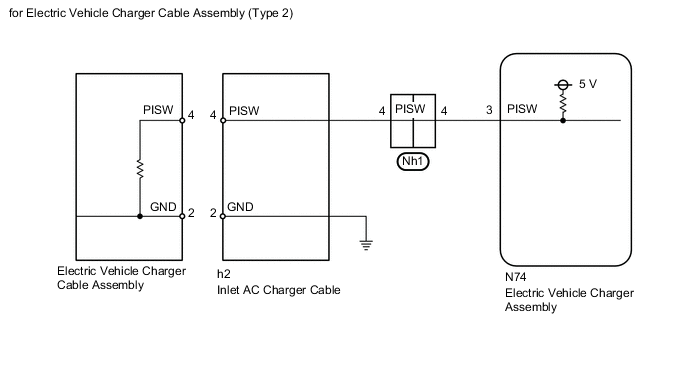
for Electric vehicle charger cable assembly (Type 2):
The electric vehicle charger assembly (charge control ECU assembly) detects the connection state of the charging cable (electric vehicle charger cable assembly) based on the PISW signal. The electric vehicle charger assembly (charge control ECU assembly) monitors and detects errors in the PISW sensor signal line.
| DTC No. | Detection Item | DTC Detection Condition | Trouble Area | MIL | Warning Indicate |
|---|---|---|---|---|---|
| P0D5611 | Charging Connector Proximity Detection Circuit Short to Ground | PISW terminal voltage remains less than 0.35 V for a certain period of time. (1 trip detection logic) |
|
Comes on | Master Warning Light: Comes on |
CONFIRMATION DRIVING PATTERN
Tech Tips
After repair has been completed, clear the DTC and then check that the vehicle has returned to normal by performing the following All Readiness check procedure.
-
Connect the GTS to the DLC3.
-
Turn the power switch on (IG) and turn the GTS on.
-
Clear the DTCs (even if no DTCs are stored, perform the clear DTC procedure).
-
Enter the following menus: Powertrain / Hybrid Control / Data List.
-
Check that "Hybrid Battery SOC" shows 70% or less.
-
Turn the power switch off and wait for 2 minutes or more.
-
Connect the electric vehicle charger cable assembly, and plug-in charge the vehicle for 30 seconds or more.
-
Disconnect the electric vehicle charger cable assembly and wait for 10 seconds or more.
-
Turn the power switch on (IG) and turn the GTS on.
-
Enter the following menus: Powertrain / Plug-in Control / Utility / All Readiness.
-
Check the DTC judgment result.
Tech Tips
-
If the judgment result shows NORMAL, the system is normal.
-
If the judgment result shows ABNORMAL, the system has a malfunction.
-
If the judgment result shows INCOMPLETE or N/A, perform driving pattern again.
-
WIRING DIAGRAM
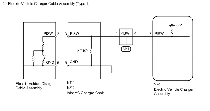
*1: w/ Charging Connector Locking System
*2: w/o Charging Connector Locking System
CAUTION / NOTICE / HINT
CAUTION:
-

Before the following operations are conducted, take precautions to prevent electric shock by turning the power switch off, wearing insulated gloves, and removing the service plug grip from HV battery.
-
Inspecting the high-voltage system
-
Disconnecting the low voltage connector of the inverter with converter assembly
-
Disconnecting the low voltage connector of the HV battery
-
Disconnecting the low voltage connector of the electric vehicle charger assembly
-
Disconnecting the low voltage connector of the solar energy control unit
-

To prevent electric shock, make sure to remove the service plug grip to cut off the high voltage circuit before servicing the vehicle.
-

After removing the service plug grip from the HV battery, put it in your pocket to prevent other technicians from accidentally reconnecting it while you are working on the high-voltage system.
-

*a Without waiting for 10 minutes After removing the service plug grip, wait for at least 10 minutes before touching any of the high-voltage connectors or terminals. After waiting for 10 minutes, check the voltage at the terminals in the inspection point in the inverter with converter assembly. The voltage should be 0 V before beginning work.
Tech Tips
Waiting for at least 10 minutes is required to discharge the high-voltage capacitor inside the inverter with converter assembly and the electric vehicle charger assembly.
Note
After turning the power switch off, waiting time may be required before disconnecting the cable from the negative (-) auxiliary battery terminal. Therefore, make sure to read the disconnecting the cable from the negative (-) auxiliary battery terminal notices before proceeding with work.
PROCEDURE
-
CHECK ELECTRIC VEHICLE CHARGER CABLE ASSEMBLY
Tech Tips
Perform the inspection with the electric vehicle charger cable assembly disconnected from the vehicle and external outlet.
-
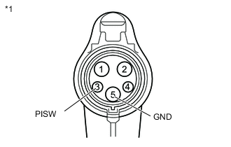
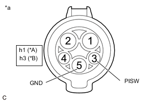
*1 Electric Vehicle Charger Cable Assembly for Electric vehicle charger cable assembly (Type 1):
-
Measure the resistance according to the value(s) in the table below.
Standard Resistance Tester Connection Condition Specified Condition 3(PISW) - 5(GND) Latch release button (PISW) is pressed 430 to 530 Ω 3(PISW) - 5(GND) Latch release button (PISW) is not pressed 135 to 165 Ω
-
-
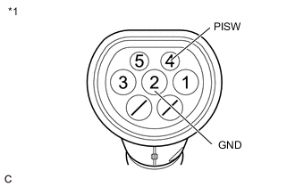
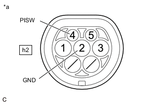
*1 Electric Vehicle Charger Cable Assembly for Electric vehicle charger cable assembly (Type 2):
-
Measure the resistance according to the value(s) in the table below.
Standard Resistance Tester Connection Condition Specified Condition 4(PISW) - 2(GND) Always 646 to 714 Ω
Result Proceed to OK NG -
NG 
REPLACE ELECTRIC VEHICLE CHARGER CABLE ASSEMBLY
OK 
-
-
CHECK HARNESS AND CONNECTOR (ELECTRIC VEHICLE CHARGER ASSEMBLY - CHARGING INLET)
CAUTION:
Be sure to wear insulated gloves.
-
Check that the service plug grip is not installed.
Note
After removing the service plug grip, do not turn the power switch on (READY), unless instructed by the repair manual because this may cause a malfunction.
Tech Tips
Perform the inspection with the electric vehicle charger cable assembly disconnected from the charging inlet.
-
Remove the EV charger duct.
-
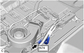
Disconnect the N74 electric vehicle charger assembly connector.
-
*A w/ Charging Connector Locking System *B w/o Charging Connector Locking System *a Inlet AC Charger Cable
(Charging Inlet)
for Electric vehicle charger cable assembly (Type 1):
-
Measure the resistance according to the value(s) in the table below.
Standard Resistance w/ Charging Connector Locking System Tester Connection Condition Specified Condition h1-3 (PISW) - h1-5 (GND) IG OFF 2.3 to 3.0 kΩ h1-3 (PISW) - Body ground IG OFF 2.3 to 3.0 kΩ w/o Charging Connector Locking System Tester Connection Condition Specified Condition h3-3 (PISW) - h1-5 (GND) IG OFF 2.3 to 3.0 kΩ h3-3 (PISW) - Body ground IG OFF 2.3 to 3.0 kΩ
-
-
*a Inlet AC Charger Cable
(Charging Inlet)
for Electric vehicle charger cable assembly (Type 2):
-
Measure the resistance according to the value(s) in the table below.
Standard Resistance Tester Connection Condition Specified Condition h2-4 (PISW) - h1-2 (GND) IG OFF 10 kΩ or higher h2-4 (PISW) - Body ground IG OFF 10 kΩ or higher
-
-
Reconnect the N74 electric vehicle charger assembly connector.
-
Install the EV charger duct.
Result Proceed to OK NG
OK
REPLACE ELECTRIC VEHICLE CHARGER ASSEMBLY Click here
NG
-
-
CHECK INLET AC CHARGER CABLE
-
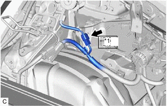
*1 Nh1 Disconnect the Nh1 inlet AC charger cable connector.
Note
If the Nh1 connector is disconnected with the auxiliary battery connected, P0D5615 may be detected. Check that the cable is disconnected from the negative (-) auxiliary battery terminal before proceeding work.
-
*A w/ Charging Connector Locking System *B w/o Charging Connector Locking System *a Inlet AC Charger Cable
(Charging Inlet)
for Electric vehicle charger cable assembly (Type 1):
-
Measure the resistance according to the value(s) in the table below.
Standard Resistance w/ Charging Connector Locking System Tester Connection Condition Specified Condition h1-3 (PISW) - h1-5 (GND) IG OFF 2.3 to 3.0 kΩ h1-3 (PISW) - Body ground IG OFF 2.3 to 3.0 kΩ w/o Charging Connector Locking System Tester Connection Condition Specified Condition h3-3 (PISW) - h1-5 (GND) IG OFF 2.3 to 3.0 kΩ h3-3 (PISW) - Body ground IG OFF 2.3 to 3.0 kΩ
-
-
*a Inlet AC Charger Cable
(Charging Inlet)
for Electric vehicle charger cable assembly (Type 2):
-
Measure the resistance according to the value(s) in the table below.
Standard Resistance Tester Connection Condition Specified Condition h2-4 (PISW) - h1-2 (GND) IG OFF 10 kΩ or higher h2-4 (PISW) - Body ground IG OFF 10 kΩ or higher
-
-
Reconnect the Nh1 inlet AC charger cable connector.
Result Proceed to OK NG
OK
REPAIR OR REPLACE HARNESS OR CONNECTOR
NG
REPLACE INLET AC CHARGER CABLE Click here
-