HYBRID CONTROL SYSTEM Inverter Low-voltage Circuit
DESCRIPTION
The cause of the malfunction may be the low-voltage circuit.
Check whether there is an open circuit in the inverter +B low-voltage power source system or a problem in the communication between the hybrid vehicle control ECU and inverter.
| Area | Inspection |
|---|---|
| Inverter +B low-voltage power source system check | Check for inverter overcurrent malfunction. |
| Communication malfunction between hybrid vehicle control ECU and MG-ECU inside inverter with converter assembly | Check for inverter overcurrent malfunction due to communication malfunction. |
| Check for short to ground in inverter +B low-voltage power source system | - |
WIRING DIAGRAM
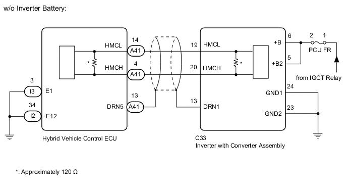
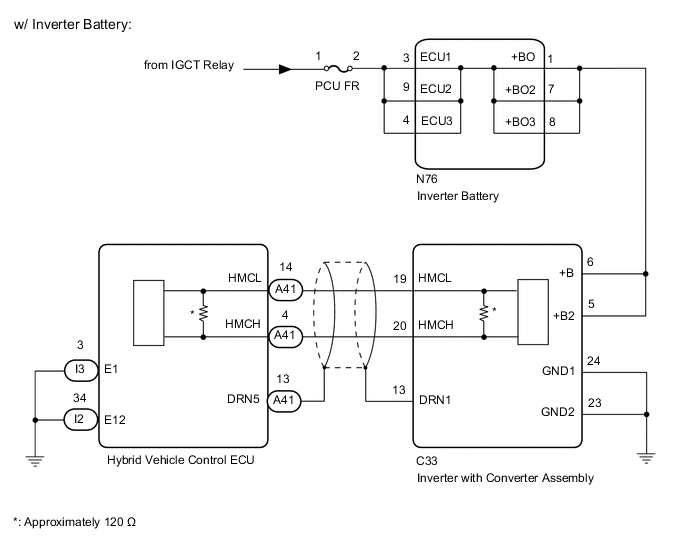
CAUTION / NOTICE / HINT
This step is referenced from the procedures for each DTC.
If the inspection results below are normal, perform the next procedure for the referenced DTC.
CAUTION:
-

-
Before the following operations are conducted, take precautions to prevent electric shock by turning the power switch off, wearing insulated gloves, and removing the service plug grip from HV battery.
-
Inspecting the high-voltage system
-
Disconnecting the low voltage connector of the inverter with converter assembly
-
Disconnecting the low voltage connector of the HV battery
-
Disconnecting the low voltage connector of the electric vehicle charger assembly
-
Disconnecting the low voltage connector of the solar energy control unit
-

To prevent electric shock, make sure to remove the service plug grip to cut off the high voltage circuit before servicing the vehicle.
-

After removing the service plug grip from the HV battery, put it in your pocket to prevent other technicians from accidentally reconnecting it while you are working on the high-voltage system.
-

*a Without waiting for 10 minutes After removing the service plug grip, wait for at least 10 minutes before touching any of the high-voltage connectors or terminals. After waiting for 10 minutes, check the voltage at the terminals in the inspection point in the inverter with converter assembly. The voltage should be 0 V before beginning work.
Tech Tips
Waiting for at least 10 minutes is required to discharge the high-voltage capacitor inside the inverter with converter assembly, the electric vehicle charger assembly and the solar energy control unit.
Note
After turning the power switch off, waiting time may be required before disconnecting the cable from the negative (-) auxiliary battery terminal. Therefore, make sure to read the disconnecting the cable from the negative (-) auxiliary battery terminal notices before proceeding with work.
Tech Tips
After the power switch is turned off, even if the cable is disconnected from the negative (-) auxiliary battery terminal, voltage will continue to be supplied to terminal +B and terminal +B2 of the inverter with converter assembly by the inverter battery (backup power supply) for approximately 2 minutes.
PROCEDURE
-
CHECK FUSE (PCU FR)
-
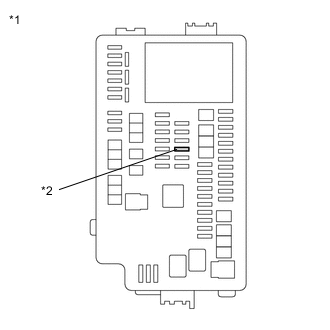
*1 No. 1 Engine Room Relay Block and No. 1 Junction Block Assembly *2 PCU FR Fuse Remove the PCU FR fuse from the No. 1 engine room relay block and No. 1 junction block assembly.
-
Measure the resistance according to the value(s) in the table below.
Standard Resistance Tester Connection Condition Specified Condition PCU FR fuse terminal Always Below 1 Ω -
Install the PCU FR fuse.
Result Proceed to OK NG
NG 
CHECK HARNESS AND CONNECTOR (INVERTER WITH CONVERTER ASSEMBLY - PCU FR FUSE) Click here
OK 
-
-
CHECK HARNESS AND CONNECTOR (INVERTER WITH CONVERTER ASSEMBLY POWER SOURCE CIRCUIT)
CAUTION:
Be sure to wear insulated gloves.
-
Check that the service plug grip is not installed.
Note
After removing the service plug grip, do not turn the power switch on (READY), unless instructed by the repair manual because this may cause a malfunction.
-
Disconnect the C33 inverter with converter assembly connector.
-
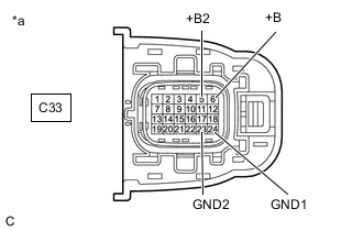
*a Front view of wire harness connector
(to Inverter with Converter Assembly)
Measure the resistance according to the value(s) in the table below.
Standard Resistance Tester Connection Condition Specified Condition C33-24 (GND1) - Body ground Power switch off Below 1 Ω C33-23 (GND2) - Body ground Power switch off Below 1 Ω -
Connect the cable to the negative (-) auxiliary battery terminal.
-
Turn the power switch on (IG).
-
Measure the voltage according to the value(s) in the table below.
Standard Voltage Tester Connection Condition Specified Condition C33-6 (+B) - Body ground Power switch on (IG) Same as auxiliary battery voltage C33-5 (+B2) - Body ground Power switch on (IG) Same as auxiliary battery voltage Note
Turning the power switch on (IG) with the inverter with converter assembly connector disconnected causes other DTCs to be stored. Clear the DTCs after performing this inspection.
-
Turn the power switch off.
-
Disconnect the cable from the negative (-) auxiliary battery terminal and wait for 2 minutes or more.
-
Reconnect the C33 inverter with converter assembly connector.
Result Proceed to OK NG
NG 
REPAIR OR REPLACE POWER SOURCE CIRCUIT
OK
-
-
CHECK HARNESS AND CONNECTOR (HYBRID VEHICLE CONTROL ECU - INVERTER WITH CONVERTER ASSEMBLY)
CAUTION:
Be sure to wear insulated gloves.
-
Check that the service plug grip is not installed.
Note
After removing the service plug grip, do not turn the power switch on (READY), unless instructed by the repair manual because this may cause a malfunction.
-
Disconnect the C33 inverter with converter assembly connector.
-
Disconnect the A41 hybrid vehicle control ECU connector.
-
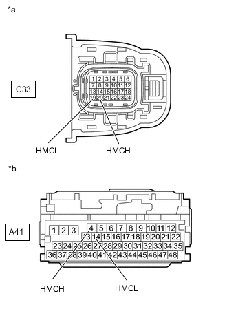
*a Front view of wire harness connector
(to Inverter with Converter Assembly)
*b Front view of wire harness connector
(to Hybrid Vehicle Control ECU)
Measure the resistance according to the value(s) in the table below.
Standard Resistance (Check for Open) Tester Connection Condition Specified Condition C33-20 (HMCH) - A41-4 (HMCH) Power switch off Below 1 Ω C33-19 (HMCL) - A41-14 (HMCL) Power switch off Below 1 Ω Standard Resistance (Check for Short) Tester Connection Condition Specified Condition C33-20 (HMCH) or A41-4 (HMCH) - Body ground and other terminals Power switch off 10 kΩ or higher C33-19 (HMCL) or A41-14 (HMCL) - Body ground and other terminals Power switch off 10 kΩ or higher -
Connect the cable to the negative (-) auxiliary battery terminal.
-
Turn the power switch on (IG).
-
Measure the voltage according to the value(s) in the table below.
Standard Voltage Tester Connection Condition Specified Condition C33-20 (HMCH) or A41-4 (HMCH) - Body ground and other terminals Power switch on (IG) Below 1 V C33-19 (HMCL) or A41-14 (HMCL) - Body ground and other terminals Power switch on (IG) Below 1 V Note
Turning the power switch on (IG) with the hybrid vehicle control ECU and inverter with converter assembly connectors disconnected causes other DTCs to be stored. Clear the DTCs after performing this inspection.
-
Turn the power switch off.
-
Disconnect the cable from the negative (-) auxiliary battery terminal and wait for 2 minutes or more.
-
Reconnect the A41 hybrid vehicle control ECU connector.
-
Reconnect the C33 inverter with converter assembly connector.
Result Proceed to OK NG
NG
REPAIR OR REPLACE HARNESS OR CONNECTOR
OK
-
-
CHECK HYBRID VEHICLE CONTROL ECU
-
Disconnect the A41 hybrid vehicle control ECU connector.
-
Measure the resistance according to the value(s) in the table below.
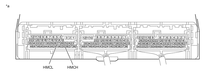
*a Component without harness connected
(Hybrid Vehicle Control ECU)
- - Standard Resistance Tester Connection Condition Specified Condition 4 (HMCH) - 14 (HMCL) Power switch off 80 to 170 Ω -
Reconnect the A41 hybrid vehicle control ECU connector.
Result Proceed to OK NG
OK
INVERTER LOW-VOLTAGE CIRCUIT NORMAL (PERFORM NEXT STEP FOR REFERENCED DTC)
NG
REPLACE HYBRID VEHICLE CONTROL ECU Click here
-
-
CHECK HARNESS AND CONNECTOR (INVERTER WITH CONVERTER ASSEMBLY - PCU FR FUSE)
CAUTION:
Be sure to wear insulated gloves.
-
Check that the service plug grip is not installed.
Note
After removing the service plug grip, do not turn the power switch on (READY), unless instructed by the repair manual because this may cause a malfunction.
-
Disconnect the C33 inverter with converter assembly connector.
-
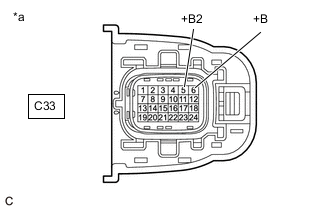
*a Front view of wire harness connector
(to Inverter with Converter Assembly)
Measure the resistance according to the value(s) in the table below.
Standard Resistance Tester Connection Condition Specified Condition C33-6 (+B) - Body ground Power switch off 10 kΩ or higher C33-5 (+B2) - Body ground Power switch off 10 kΩ or higher -
Reconnect the C33 inverter with converter assembly connector.
Result Result Proceed to OK A NG (w/o Inverter Battery) B NG (w/ Inverter Battery) C
B
REPAIR OR REPLACE HARNESS OR CONNECTOR Click here
C
CHECK HARNESS AND CONNECTOR (INVERTER BATTERY - BODY GROUND) Click here
A
-
-
REFER TO REPLACE INVERTER WITH CONVERTER ASSEMBLY PARTS
Result Proceed to NEXT
NEXT
REPLACE FUSE (PCU FR)
-
REPAIR OR REPLACE HARNESS OR CONNECTOR
Result Proceed to NEXT
NEXT
REPLACE FUSE (PCU FR)
-
CHECK HARNESS AND CONNECTOR (INVERTER BATTERY - BODY GROUND)
CAUTION:
Be sure to wear insulated gloves.
-
Check that the service plug grip is not installed.
Note
After removing the service plug grip, do not turn the power switch on (READY), unless instructed by the repair manual because this may cause a malfunction.
-
Disconnect the C33 inverter with converter assembly connector.
-
Disconnect the N76 inverter battery connector.
-
Remove the PCU FR fuse from the No. 1 engine room relay block and No. 1 junction block assembly.
-
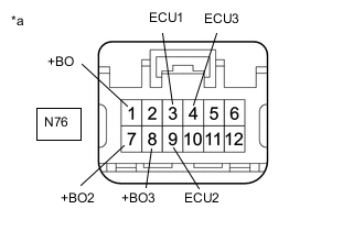
*a Front view of wire harness connector
(to Inverter Battery)
Measure the resistance according to the value(s) in the table below.
Standard Resistance Tester Connection Condition Specified Condition N76-3 (ECU1) - Body ground Power switch off 10 kΩ or higher N76-9 (ECU2) - Body ground Power switch off 10 kΩ or higher N76-4 (ECU3) - Body ground Power switch off 10 kΩ or higher N76-1 (+BO) - Body ground Power switch off 10 kΩ or higher N76-7 (+BO2) - Body ground Power switch off 10 kΩ or higher N76-8 (+BO3) - Body ground Power switch off 10 kΩ or higher -
Reinstall the PCU FR fuse.
-
Reconnect the N76 inverter battery connector.
-
Reconnect the C33 inverter with converter assembly connector.
Result Proceed to OK NG
NG
REPAIR OR REPLACE HARNESS OR CONNECTOR Click here
OK
-
-
REPLACE INVERTER BATTERY
Result Proceed to NEXT
NEXT
REPLACE FUSE (PCU FR)
-
REPAIR OR REPLACE HARNESS OR CONNECTOR
Result Proceed to NEXT
NEXT
REPLACE FUSE (PCU FR)