HYBRID CONTROL SYSTEM Pattern Select Switch EV/HV Mode Circuit
DESCRIPTION
-
EV mode
When a sufficient amount of electricity is remaining after charging, EV driving is performed using electricity stored in the HV battery.
Depending on the situation, EV driving may be canceled and both gasoline engine and electric motor are used (HV mode).
When in EV mode, the "EV MODE" indicator illuminates.
-
HV battery charge mode
Electricity generated in the gasoline engine can be stored in the HV battery by switching to the HV battery charge mode when electricity needed for EV driving is not remaining.
When in the HV battery charge mode, the HV battery can be charged while driving. However, the gasoline engine runs to charge the battery and fuel consumption becomes higher compared with driving in HV mode.
When in the HV battery charge mode, the "CHG MODE" indicator illuminates.
WIRING DIAGRAM
Figure 1. for LHD
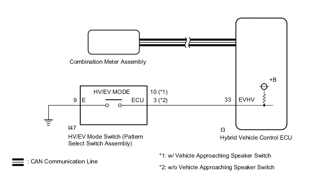
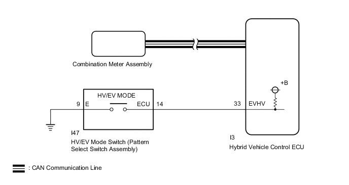
Figure 2. for RHD
PROCEDURE
-
ASK ABOUT VEHICLE CONDITION
-
Check if a buzzer sounded and a message was displayed on the multi-information display when operating the HV/EV mode switch (pattern select switch assembly).
Result Result Proceed to No buzzer sounded and no message was displayed on multi-information display. A A buzzer sounded and a message was displayed on multi-information display. B Tech Tips
If a buzzer sounds and a message is displayed on the multi-information display, the EV mode entry conditions have not been met.
B 
END
A 
-
-
READ VALUE USING GTS (CAN BUS CHECK)
-
Connect the GTS to the DLC3.
-
Turn the power switch on (IG).
-
Turn the GTS on.
-
Enter the following menus: System Select / CAN Bus Check.
CAN Bus CheckResult Result Proceed to All of the ECUs and sensors that are currently connected to the CAN communication system are displayed. A None of the ECUs and sensors that are currently connected to the CAN communication system are displayed, or some of them are not displayed. B -
Turn the power switch off.
B
GO TO CAN COMMUNICATION SYSTEM Click here
A
-
-
CHECK DTC OUTPUT (HEALTH CHECK)
-
Connect the GTS to the DLC3.
-
Turn the power switch on (IG).
-
Turn the GTS on.
-
Enter the following menus: System Select / Health Check.
-
Check for DTCs.
Result Result Proceed to No DTCs output A DTCs output B -
Turn the power switch off.
B
GO TO DTC CHART
A
-
-
READ VALUE USING GTS (HV/EV MODE SWITCH, EV MODE STATUS)
-
Connect the GTS to the DLC3.
-
Turn the power switch on (IG).
-
Turn the GTS on.
-
Enter the following menus: Powertrain / Hybrid Control / Data List / HV/EV Mode Switch, EV Mode Status.
Powertrain > Hybrid Control > Data ListTester Display HV/EV Mode Switch EV Mode Status -
Read the value displayed on the GTS.
Powertrain > Hybrid Control > Data ListTester Display Measurement Item Range Normal Condition HV/EV Mode Switch HV/EV mode switch (pattern select switch assembly) condition ON or OFF HV/EV mode switch (pattern select switch assembly) being pushed and held: ON
HV/EV mode switch (pattern select switch assembly) not pushed: OFF
EV Mode Status EV mode status Normal / EV Mode / Changing to HV Mode from EV Mode / Changing to EV Mode from HV Mode / EV CITY Mode / Changing to HV Mode from EV CITY Mode / Battery Charge Mode / Changing to HV Mode from Battery Charge Mode / Standby for Battery Charge Mode / EV AUTO Mode / Changing to HV Mode from EV AUTO Mode In EV drive mode: EV Mode Result Result Proceed to The display changes according to the HV/EV mode switch (pattern select switch assembly) operation. A The display does not change according to the HV/EV mode switch (pattern select switch assembly) operation. B -
Turn the power switch off.
A
CHECK FOR INTERMITTENT PROBLEMS Click here
B
-
-
INSPECT HV/EV MODE SWITCH (PATTERN SELECT SWITCH ASSEMBLY)
-
Remove the HV/EV mode switch (pattern select switch assembly).
-
for LHD:
-
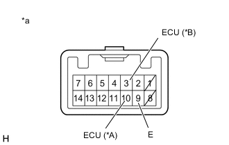
*A w/ Vehicle Approaching Speaker Switch *B w/o Vehicle Approaching Speaker Switch *a Component without harness connected
(HV/EV Mode Switch (Pattern Select Switch Assembly))
Measure the resistance according to the value(s) in the table below.
Standard Resistance w/ Vehicle Approaching Speaker Switch Tester Connection Condition Specified Condition 10 (ECU) - 9 (E) HV/EV mode switch (pattern select switch assembly) being pushed and held Below 50 Ω HV/EV mode switch (pattern select switch assembly) not pushed 10 kΩ or higher w/o Vehicle Approaching Speaker Switch Tester Connection Condition Specified Condition 3 (ECU) - 9 (E) HV/EV mode switch (pattern select switch assembly) being pushed and held Below 50 Ω HV/EV mode switch (pattern select switch assembly) not pushed 10 kΩ or higher
-
-
for RHD:
-
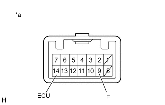
*a Component without harness connected
(HV/EV Mode Switch (Pattern Select Switch Assembly))
Measure the resistance according to the value(s) in the table below.
Standard Resistance Tester Connection Condition Specified Condition 14 (ECU) - 9 (E) HV/EV mode switch (pattern select switch assembly) being pushed and held Below 50 Ω HV/EV mode switch (pattern select switch assembly) not pushed 10 kΩ or higher
-
-
Install the HV/EV mode switch (pattern select switch assembly).
Result Proceed to OK NG
NG
REPLACE HV/EV MODE SWITCH (PATTERN SELECT SWITCH ASSEMBLY) Click here
OK
-
-
CHECK HARNESS AND CONNECTOR (HV/EV MODE SWITCH (PATTERN SELECT SWITCH ASSEMBLY) - BODY GROUND)
-
Disconnect the I47 HV/EV mode switch (pattern select switch assembly) connector.
-
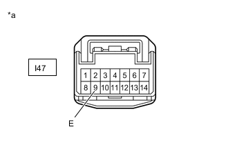
*a Front view of wire harness connector
(to HV/EV Mode Switch (Pattern Select Switch Assembly))
Measure the resistance according to the value(s) in the table below.
Standard Resistance Tester Connection Condition Specified Condition I47-9 (E) - Body ground Always Below 1 Ω -
Reconnect the I47 HV/EV mode switch (pattern select switch assembly) connector.
Result Proceed to OK NG
NG
REPAIR OR REPLACE HARNESS OR CONNECTOR
OK
-
-
CHECK HARNESS AND CONNECTOR (HYBRID VEHICLE CONTROL ECU - HV/EV MODE SWITCH (PATTERN SELECT SWITCH ASSEMBLY))
-
Disconnect the I3 hybrid vehicle control ECU connector.
-
Disconnect the I47 HV/EV mode switch (pattern select switch assembly) connector.
-
for LHD:
-
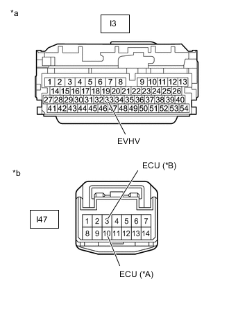
*A w/ Vehicle Approaching Speaker Switch *B w/o Vehicle Approaching Speaker Switch *a Front view of wire harness connector
(to Hybrid Vehicle Control ECU)
*b Front view of wire harness connector
(to HV/EV Mode Switch (Pattern Select Switch Assembly))
Measure the resistance according to the value(s) in the table below.
Standard Resistance w/ Vehicle Approaching Speaker Switch Tester Connection Condition Specified Condition I3-33 (EVHV) - I47-10 (ECU) Always Below 1 Ω I3-33 (EVHV) or I47-10 (ECU) - Body ground Always 10 kΩ or higher w/o Vehicle Approaching Speaker Switch Tester Connection Condition Specified Condition I3-33 (EVHV) - I47-3 (ECU) Always Below 1 Ω I3-33 (EVHV) or I47-3 (ECU) - Body ground Always 10 kΩ or higher
-
-
for RHD:
-
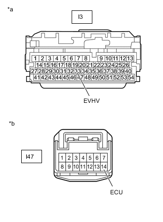
*a Front view of wire harness connector
(to Hybrid Vehicle Control ECU)
*b Front view of wire harness connector
(to HV/EV Mode Switch (Pattern Select Switch Assembly))
Measure the resistance according to the value(s) in the table below.
Standard Resistance Tester Connection Condition Specified Condition I3-33 (EVHV) - I47-14 (ECU) Always Below 1 Ω I3-33 (EVHV) or I47-14 (ECU) - Body ground Always 10 kΩ or higher
-
-
Reconnect the I47 EV/HV mode switch (pattern select switch assembly) connector.
-
Reconnect the I3 hybrid vehicle control ECU connector.
Result Proceed to OK NG
OK
REPLACE HYBRID VEHICLE CONTROL ECU Click here
NG
REPAIR OR REPLACE HARNESS OR CONNECTOR
-