HYBRID CONTROL SYSTEM Drive Mode Select Switch Circuit
DESCRIPTION
When the drive mode select switch (pattern select switch assembly) is operated, a switch signal is sent to the hybrid vehicle control ECU and the hybrid vehicle control ECU changes the drive mode.
Tech Tips
-
If the power switch is turned off while in POWER mode, the drive mode will automatically be changed to NORMAL mode when the power switch is turned on (IG).
-
If the power switch is turned off while in NORMAL mode or ECO mode, the selected drive mode will resume when the power switch is turned on (IG).
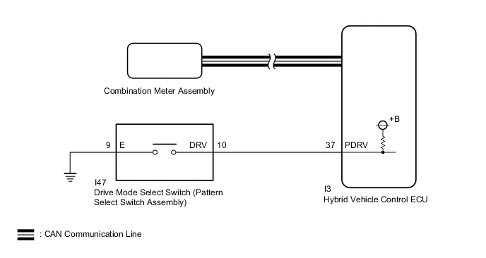
WIRING DIAGRAM
Figure 1. for LHD
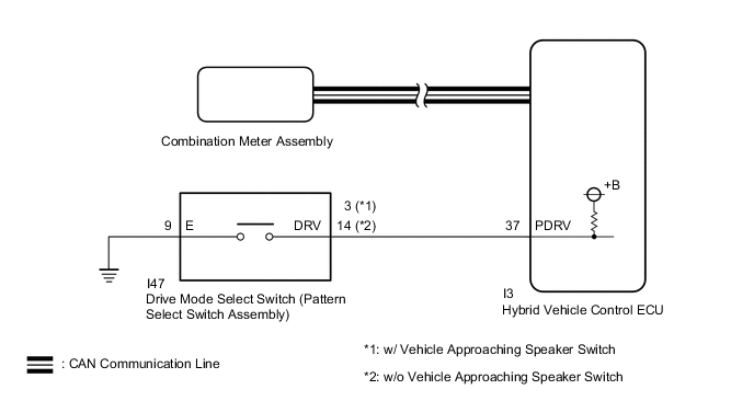
Figure 2. for RHD
PROCEDURE
-
READ VALUE USING GTS (CAN BUS CHECK)
Result Proceed to A B
-
Connect the GTS to the DLC3.
-
Turn the power switch on (IG).
-
Turn the GTS on.
-
Enter the following menus: System Select / CAN Bus Check.
CAN Bus CheckResult Result Proceed to All of the ECUs and sensors that are currently connected to the CAN communication system are displayed. A None of the ECUs and sensors that are currently connected to the CAN communication system are displayed, or some of them are not displayed. B -
Turn the power switch off.
B 
GO TO CAN COMMUNICATION SYSTEM Click here
A 
-
-
CHECK DTC OUTPUT (HEALTH CHECK)
Result Proceed to A B
-
Connect the GTS to the DLC3.
-
Turn the power switch on (IG).
-
Turn the GTS on.
-
Enter the following menus: System Select / Health Check.
-
Check for DTCs.
Result Result Proceed to No DTCs output A DTCs output B -
Turn the power switch off.
B
GO TO DTC CHART
A
-
-
CHECK DRIVE MODE STATUS (NORMAL MODE, ECO MODE, POWER MODE)
-
Turn the power switch on (IG).
-
Operate the drive mode select switch (pattern select switch assembly) to change the drive mode.
-
Check that the drive mode indicator is displayed on the multi-information display and changes according to the selected drive mode.
Result Result Proceed to The display changes according to the drive mode select switch (pattern select switch assembly) operation. A The display does not change according to the drive mode select switch (pattern select switch assembly) operation. B -
Turn the power switch off.
A
GO TO PROBLEM SYMPTOMS TABLE Click here
B
-
-
READ VALUE USING GTS (POWERTRAIN DRIVE MODE SWITCH)
-
Connect the GTS to the DLC3.
-
Turn the power switch on (IG).
-
Turn the GTS on.
-
Enter the following menus: Powertrain / Hybrid Control / Data List / Powertrain Drive Mode Switch.
Powertrain > Hybrid Control > Data ListTester Display Powertrain Drive Mode Switch -
Read the value displayed on the GTS.
Powertrain > Hybrid ControlTester Display Measurement Item Range Normal Condition Powertrain Drive Mode Switch Drive mode select switch (pattern select switch assembly) condition ON or OFF Drive mode select switch (pattern select switch assembly) not operated: OFF
Drive mode select switch (pattern select switch assembly) being pushed and held: ON
Result Result Proceed to The display changes according to the drive mode select switch (pattern select switch assembly) operation. A The display does not change according to the drive mode select switch (pattern select switch assembly) operation. B -
Turn the power switch off.
A
CHECK METER / GAUGE SYSTEM Click here
B
-
-
INSPECT DRIVE MODE SELECT SWITCH (PATTERN SELECT SWITCH ASSEMBLY)
-
Remove the drive mode select switch (pattern select switch assembly).
-
for LHD:
-
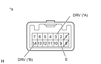
*A w/ Vehicle Approaching Speaker Switch *B w/o Vehicle Approaching Speaker Switch *a Component without harness connected
(Drive Mode Select Switch (Pattern Select Switch Assembly))
Measure the resistance according to the value(s) in the table below.
Standard Resistance w/ Vehicle Approaching Speaker Switch Tester Connection Condition Specified Condition 3 (DRV) - I47-9 (E) Drive mode select switch (pattern select switch assembly) being pushed and held Below 50 Ω Drive mode select switch (pattern select switch assembly) not pushed 10 kΩ or higher w/o Vehicle Approaching Speaker Switch Tester Connection Condition Specified Condition 14 (DRV) - I47-9 (E) Drive mode select switch (pattern select switch assembly) being pushed and held Below 50 Ω Drive mode select switch (pattern select switch assembly) not pushed 10 kΩ or higher
-
-
for RHD:
-
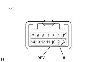
*a Component without harness connected
(Drive Mode Select Switch (Pattern Select Switch Assembly))
Measure the resistance according to the value(s) in the table below.
Standard Resistance Tester Connection Condition Specified Condition 10 (DRV) - 9 (E) Drive mode select switch (pattern select switch assembly) being pushed and held Below 50 Ω Drive mode select switch (pattern select switch assembly) not pushed 10 kΩ or higher
-
-
Install the drive mode select switch (pattern select switch assembly).
Result Proceed to OK NG
NG
REPLACE DRIVE MODE SELECT SWITCH (PATTERN SELECT SWITCH ASSEMBLY) Click here
OK
-
-
CHECK HARNESS AND CONNECTOR (DRIVE MODE SELECT SWITCH (PATTERN SELECT SWITCH ASSEMBLY) - BODY GROUND)
-
Disconnect the I47 drive mode select switch (pattern select switch assembly) connector.
-
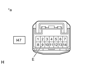
*a Front view of wire harness connector
(to Drive Mode Select Switch (Pattern Select Switch Assembly))
Measure the resistance according to the value(s) in the table below.
Standard Resistance Tester Connection Condition Specified Condition I47-9 (E) - Body ground Always Below 1 Ω -
Reconnect the I47 drive mode select switch (pattern select switch assembly) connector.
Result Proceed to OK NG
NG
REPAIR OR REPLACE HARNESS OR CONNECTOR
OK
-
-
CHECK HARNESS AND CONNECTOR (HYBRID VEHICLE CONTROL ECU - DRIVE MODE SELECT SWITCH (PATTERN SELECT SWITCH ASSEMBLY))
-
Disconnect the I3 hybrid vehicle control ECU connector.
-
Disconnect the I47 drive mode select switch (pattern select switch assembly) connector.
-
for LHD:
-
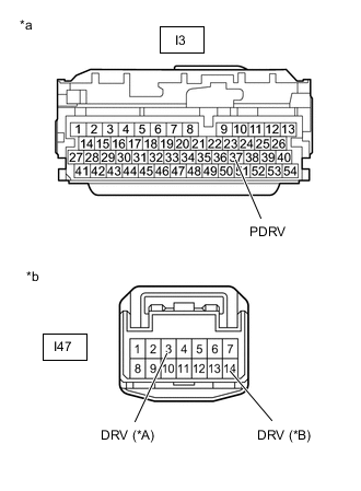
*A w/ Vehicle Approaching Speaker Switch *B w/o Vehicle Approaching Speaker Switch *a Front view of wire harness connector
(to Hybrid Vehicle Control ECU)
*b Front view of wire harness connector
(to Drive Mode Select Switch (Pattern Select Switch Assembly))
Measure the resistance according to the value(s) in the table below.
Standard Resistance w/ Vehicle Approaching Speaker Switch Tester Connection Condition Specified Condition I3-37 (PDRV) - I47-3 (DRV) Always Below 1 Ω I3-37 (PDRV) or I47-3 (DRV) - Body ground Always 10 kΩ or higher w/o Vehicle Approaching Speaker Switch Tester Connection Condition Specified Condition I3-37 (PDRV) - I47-14 (DRV) Always Below 1 Ω I3-37 (PDRV) or I47-14 (DRV) - Body ground Always 10 kΩ or higher
-
-
for RHD:
-
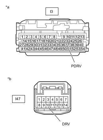
*a Front view of wire harness connector
(to Hybrid Vehicle Control ECU)
*b Front view of wire harness connector
(to Drive Mode Select Switch (Pattern Select Switch Assembly))
Measure the resistance according to the value(s) in the table below.
Standard Resistance Tester Connection Condition Specified Condition I3-37 (PDRV) - I47-10 (DRV) Always Below 1 Ω I3-37 (PDRV) or I47-10 (DRV) - Body ground Always 10 kΩ or higher
-
-
Reconnect the I47 drive mode select switch (pattern select switch assembly) connector.
-
Reconnect the I3 hybrid vehicle control ECU connector.
Result Proceed to OK NG
OK
REPLACE HYBRID VEHICLE CONTROL ECU Click here
NG
REPAIR OR REPLACE HARNESS OR CONNECTOR
-