HYBRID CONTROL SYSTEM, Diagnostic DTC:P260031
| DTC Code | DTC Name |
|---|---|
| P260031 | Motor/Generator Coolant Pump "A" Control Circuit No Signal |
DESCRIPTION
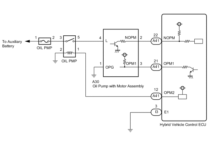
The hybrid vehicle control ECU detects the generator (MG1) and motor (MG2) temperature based on signals from the generator and motor temperature sensors and activates the OIL PMP relay and oil pump driver (oil pump with motor assembly).
The hybrid vehicle control ECU monitors NOPM signals from the oil pump driver and detects malfunctions.
| DTC No. | Detection Item | DTC Detection Condition | Trouble Area | MIL | Warning Indicate |
|---|---|---|---|---|---|
| P260031 | Motor/Generator Coolant Pump "A" Control Circuit No Signal | When the OIL PMP relay is on, the NOPM input pulse signal is not output. (1 trip detection logic) |
|
Does not come on | Master Warning Light: Comes on |
| DTC No. | Data List |
|---|---|
| P260031 |
|
Tech Tips
The oil pump with motor assembly cannot be activated only with the OIL PMP relay on. It is activated after receiving the command signals (OPM1) from the hybrid vehicle control ECU.
CONFIRMATION DRIVING PATTERN
Tech Tips
After repair has been completed, clear the DTC and then check that the vehicle has returned to normal by performing the following All Readiness check procedure.
-
Connect the GTS to the DLC3.
-
Turn the power switch on (IG) and turn the GTS on.
-
Clear the DTCs (even if no DTCs are stored, perform the clear DTC procedure).
-
Turn the power switch on (IG) and turn the GTS on.
-
Enter the following menus: Powertrain / Hybrid Control / Active Test / T/M Cooler Oil Pump.
-
According to the display on the GTS, perform the Active Test and set the duty to 95 %.
Tech Tips
The Active Test cannot be performed if the duty ratio is set to 50 % or lower or 95 % or higher, or if the ambient temperature is -10 °C (14 °F) or lower.
-
According to the display on the GTS, read the Data List and check that the value of "Motor/Generator Cooling Oil Pump Motor Revolution" is between 500 rpm and 7000 rpm.
WIRING DIAGRAM
PROCEDURE
-
CHECK HYBRID VEHICLE TRANSAXLE ASSEMBLY (TRANSMISSION FLUID TEMPERATURE SENSOR)
Tech Tips
The transmission fluid temperature sensor value is used to detect DTC P260031. Check that the transmission fluid temperature sensor operates normally, as the detection condition for DTC P260031 may be mistakenly detected due to a malfunction in the transmission fluid temperature sensor.
-
Following the troubleshooting procedures for the ambient temperature sensor, check that the transmission fluid temperature sensor operates normally.
Result Proceed to OK NG
NG 
REPLACE HYBRID VEHICLE TRANSAXLE ASSEMBLY Click here
OK 
-
-
CHECK OIL PIPE
-
Check that there is no clogging in the oil pipes connected to the oil pump with motor assembly, oil cooler assembly, and hybrid vehicle transaxle assembly.
Result Proceed to OK NG
NG
REPAIR OR REPLACE OIL PIPE
OK
-
-
CHECK CONNECTOR CONNECTION CONDITION (OIL PUMP WITH MOTOR ASSEMBLYCONNECTOR)
-
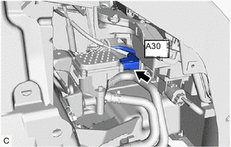
Check the connector connections and contact pressure of the relevant terminals for the A30 oil pump with motor assembly connector.
OK The connector is connected securely and there are no contact problems. Result Proceed to OK NG
NG
CONNECT SECURELY
OK
-
-
CHECK CONNECTOR CONNECTION CONDITION (HYBRID VEHICLE CONTROL ECU CONNECTOR)
Result Proceed to OK NG
-
Check the connector connections and contact pressure of the relevant terminals for the hybrid vehicle control ECU connectors.
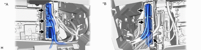
*A for LHD *B for RHD OK The connectors are connected securely and there are no contact pressure problems. Result Proceed to OK NG
NG
CONNECT SECURELY
OK
-
-
CHECK FUSE (OIL PMP)
-
Remove the OIL PMP fuse from the No. 1 engine room relay block and No. 1 junction block assembly.
-
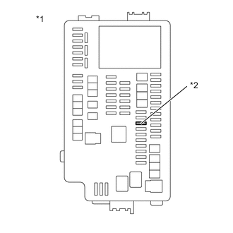
*1 No. 1 Engine Room Relay Block and No. 1 Junction Block Assembly *2 OIL PMP Fuse Measure the resistance according to the value(s) in the table below.
Standard Resistance Tester Connection Condition Specified Condition OIL PMP fuse Always Below 1 Ω -
Install the OIL PMP fuse to the No. 1 engine room relay block and No. 1 junction block assembly.
Result Proceed to OK NG
NG
REPLACE FUSE (OIL PMP)
OK
-
-
INSPECT OIL PMP RELAY
-
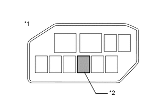
*1 No. 2 Relay Block Assembly *2 OIL PMP Relay Remove the OIL PMP relay from the No. 2 relay block assembly.
-
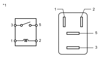
*1 OIL PMP Relay Measure the resistance according to the value(s) in the table below.
Standard Resistance Tester Connection Condition Specified Condition 3 - 5 Auxiliary battery voltage not applied between terminals 1 and 2 10 kΩ or higher Auxiliary battery voltage applied between terminals 1 and 2 Below 1 Ω -
Install the OIL PMP relay.
Result Proceed to OK NG
NG
REPLACE OIL PMP RELAY
OK
-
-
CHECK HARNESS AND CONNECTOR (OIL PMP FUSE - OIL PMP RELAY)
-
Remove the OIL PMP fuse from the No. 1 engine room relay block and No. 1 junction block assembly.
-
Remove the OIL PMP relay from the No. 2 relay block assembly.
-
Measure the resistance according to the value(s) in the table below.
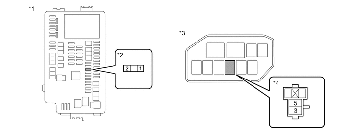
*1 No. 1 Engine Room Relay Block and No. 1 Junction Block Assembly *2 OIL PMP Fuse *3 No. 2 Relay Block Assembly *4 OIL PMP Relay Standard Resistance (Check for Open) Tester Connection Condition Specified Condition 2 (OIL PMP fuse) - 3 (OIL PMP relay) Power switch off Below 1 Ω Standard Resistance (Check for Short) Tester Connection Condition Specified Condition 2 (OIL PMP fuse) or 3 (OIL PMP relay) - Body ground and other terminals Power switch off 10 kΩ or higher Note
Do not apply excessive force when using the probes of the tester to perform the inspection. If excessive force is used, the terminals will be damaged.
-
Install the OIL PMP relay.
-
Install the OIL PMP fuse.
Result Proceed to OK NG
NG
REPAIR OR REPLACE HARNESS OR CONNECTOR
OK
-
-
CHECK HARNESS AND CONNECTOR (OIL PMP RELAY - BODY GROUND)
-
Remove the OIL PMP relay from the No. 2 relay block assembly.
-
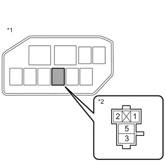
*1 No. 2 Relay Block Assembly *2 OIL PMP Relay Measure the resistance according to the value(s) in the table below.
Standard Resistance Tester Connection Condition Specified Condition 2 (OIL PMP relay) - Body ground Power switch off Below 1 Ω Note
Do not apply excessive force when using the probes of the tester to perform the inspection. If excessive force is used, the terminals will be damaged.
-
Install the OIL PMP relay.
Result Proceed to OK NG
NG
REPAIR OR REPLACE HARNESS OR CONNECTOR
OK
-
-
CHECK HARNESS AND CONNECTOR (OIL PUMP WITH MOTOR ASSEMBLY - OIL PMP RELAY)
-
Disconnect the A30 oil pump with motor assembly connector.
-
Remove the OIL PMP relay from the No. 2 relay block assembly.
-
Measure the resistance according to the value(s) in the table below.
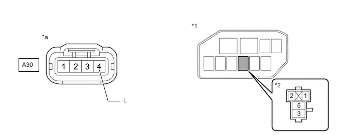
*1 No. 2 Relay Block Assembly *2 OIL PMP Relay *a Front view of wire harness connector
(to Oil Pump with Motor Assembly)
- - Standard Resistance (Check for Open) Tester Connection Condition Specified Condition A30-4 (L) - 5 (OIL PMP relay) Power switch off Below 1 Ω Standard Resistance (Check for Short) Tester Connection Condition Specified Condition A30-4 (L) or 5 (OIL PMP relay) - Body ground and other terminals Power switch off 10 kΩ or higher Note
Do not apply excessive force when using the probes of the tester to perform the inspection. If excessive force is used, the terminals will be damaged.
-
Install the OIL PMP relay.
-
Reconnect the A30 oil pump with motor assembly connector.
Result Proceed to OK NG
NG
REPAIR OR REPLACE HARNESS OR CONNECTOR
OK
-
-
CHECK HARNESS AND CONNECTOR (HYBRID VEHICLE CONTROL ECU - OIL PMP RELAY)
-
Disconnect the A41 hybrid vehicle control ECU connector.
-
Remove the OIL PMP relay from the No. 2 relay block Assembly.
-
Measure the resistance according to the value(s) in the table below.
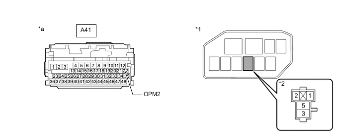
*1 No. 2 Relay Block Assembly *2 OIL PMP Relay *a Front view of wire harness connector
(to Hybrid Vehicle Control ECU)
- - Standard Resistance (Check for Open) Tester Connection Condition Specified Condition A41-12 (OPM2) - 1 (OIL PMP relay) Power switch off Below 1 Ω Standard Resistance (Check for Short) Tester Connection Condition Specified Condition A41-12 (OPM2) or 1 (OIL PMP relay) - Body ground and other terminals Power switch off 10 kΩ or higher Note
Do not apply excessive force when using the probes of the tester to perform the inspection. If excessive force is used, the terminals will be damaged.
-
Install the OIL PMP relay.
-
Reconnect the A41 hybrid vehicle control ECU connector.
Result Proceed to OK NG
NG
REPAIR OR REPLACE HARNESS OR CONNECTOR
OK
-
-
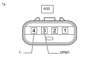
CHECK HARNESS AND CONNECTOR (OIL PUMP WITH MOTOR ASSEMBLY - BODY GROUND)
-
Disconnect the A30 oil pump with motor assembly connector.
-
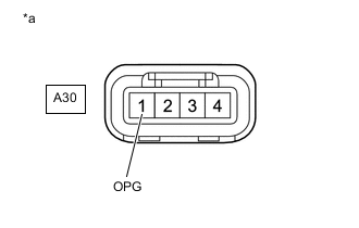
*a Front view of wire harness connector
(to Oil Pump with Motor Assembly)
Measure the resistance according to the value(s) in the table below.
Standard Resistance Tester Connection Condition Specified Condition A30-1 (OPG) - Body ground Power switch off Below 1 Ω -
Reconnect the A30 oil pump with motor assembly connector.
Result Proceed to OK NG
NG
REPAIR OR REPLACE HARNESS OR CONNECTOR
OK
-
-
CHECK HARNESS AND CONNECTOR (HYBRID VEHICLE CONTROL ECU - OIL PUMP WITH MOTOR ASSEMBLY)
-
Disconnect the A41 hybrid vehicle control ECU connector.
-
Disconnect the A30 oil pump with motor assembly connector.
-
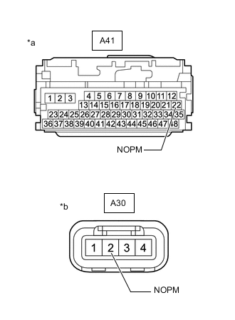
*a Front view of wire harness connector
(to Hybrid Vehicle Control ECU)
*b Front view of wire harness connector
(to Oil Pump with Motor Assembly)
Measure the resistance according to the value(s) in the table below.
Standard Resistance (Check for Open) Tester Connection Condition Specified Condition A41-22 (NOPM) - A30-2 (NOPM) Power switch off Below 1 Ω Standard Resistance (Check for Short) Tester Connection Condition Specified Condition A41-22 (NOPM) or A30-2 (NOPM) - Body ground and other terminals Power switch off 10 kΩ or higher -
Reconnect the A30 oil pump with motor assembly connector.
-
Reconnect the A41 hybrid vehicle control ECU connector.
Result Proceed to OK NG
NG
REPAIR OR REPLACE HARNESS OR CONNECTOR
OK
-
-
CHECK HARNESS AND CONNECTOR (HYBRID VEHICLE CONTROL ECU - OIL PUMP WITH MOTOR ASSEMBLY)
-
Disconnect the A41 hybrid vehicle control ECU connector.
-
Disconnect the A30 oil pump with motor assembly connector.
-
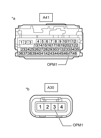
*a Front view of wire harness connector
(to Hybrid Vehicle Control ECU)
*b Front view of wire harness connector
(to Oil Pump with Motor Assembly)
Measure the resistance according to the value(s) in the table below.
Standard Resistance (Check for Open) Tester Connection Condition Specified Condition A41-21 (OPM1) - A30-3 (OPM1) Power switch off Below 1 Ω Standard Resistance (Check for Short) Tester Connection Condition Specified Condition A41-21 (OPM1) or A30-3 (OPM1) - Body ground and other terminals Power switch off 10 kΩ or higher -
Connect the cable to the negative (-) auxiliary battery terminal.
-
Turn the power switch on (IG).
-
Measure the voltage according to the value(s) in the table below.
Standard Voltage Tester Connection Condition Specified Condition A41-21 (OPM1) or A30-3 (OPM1) - Body ground Power switch on (IG) Below 1 V Note
Turning the power switch on (IG) with the hybrid vehicle control ECU and oil pump with motor assembly connectors disconnected causes other DTCs to be stored. Clear the DTCs after performing this inspection.
-
Turn the power switch off.
-
Disconnect the cable from the negative (-) auxiliary battery terminal.
-
Reconnect the A30 oil pump with motor assembly connector.
-
Reconnect the A41 hybrid vehicle control ECU connector.
Result Proceed to OK NG
NG
REPAIR OR REPLACE HARNESS OR CONNECTOR
OK
-
-
INSPECT OIL PUMP WITH MOTOR ASSEMBLY
-
Disconnect the A30 oil pump with motor assembly connector.
-
*a Component without harness connected
(Oil Pump with Motor Assembly)
Measure the resistance according to the value(s) in the table below.
Standard Resistance Tester Connection Condition Specified Condition A30-3 (OPM1) - A30-4 (L) Power switch off 10 kΩ or higher A30-3 (OPM1) - Body ground Power switch off 10 kΩ or higher -
Reconnect the A30 oil pump with motor assembly connector.
Result Proceed to OK NG
OK
REPLACE HYBRID VEHICLE CONTROL ECU Click here
NG
REPLACE OIL PUMP WITH MOTOR ASSEMBLY Click here
-