HYBRID CONTROL SYSTEM, Diagnostic DTC:P1ECB00
| DTC Code | DTC Name |
|---|---|
| P1ECB00 | Hybrid/EV Powertrain Control Module Processor and Monitoring Processor Solar Charging Permission Signal Stuck Off |
DTC SUMMARY
-
MALFUNCTION DESCRIPTION
When solar charging is started, the hybrid vehicle control ECU checks the solar charge permission signal (SSEN) output to the solar energy control unit and the answer back signal output by the solar energy control unit.
This DTC is stored if an answer back signal from the solar energy control unit is not received by the hybrid vehicle control ECU when it outputs the solar charge permission signal (SSEN). In this case, the operation of the solar charge permission signal cannot be assured.
The cause of this malfunction may be one of the following:
-
Hybrid Vehicle Control ECU malfunction
Hybrid vehicle control ECU internal malfunction
-
The connectors are not connected properly
-
Foreign matter or water on the connector terminals
-
Open or short in wire harness
Wire harness between the solar energy control unit and hybrid vehicle control ECU
-
Solar energy control unit malfunction
Solar energy control unit internal malfunction
-
Communication malfunction between the solar energy control unit and hybrid vehicle control ECU
Communication Error
-
DESCRIPTION
Refer to the description for DTC P1EC900.
| DTC No. | Detection Item | DTC Detection Condition | Trouble Area | MIL | Warning Indicate |
|---|---|---|---|---|---|
| P1ECB00 | Hybrid/EV Powertrain Control Module Processor and Monitoring Processor Solar Charging Permission Signal Stuck Off | An answer back signal is not received from the solar energy control unit when the hybrid vehicle control ECU outputs the solar charge permission signal. (1 trip detection logic) |
|
Does not come on | Solar Charging Warning Light: Comes on |
| DTC No. | Data List |
|---|---|
| P1ECB00 |
|
CONFIRMATION DRIVING PATTERN
Tech Tips
After repair has been completed, clear the DTC and then check that the vehicle has returned to normal by performing the following All Readiness check procedure.
-
Park the vehicle in an area where the solar radiation will be steady.
Weather Clear or mostly clear and sunny Time Between 11:00 and 14:00 Place An area where sunlight strikes the solar roof directly Tech Tips
-
Make sure no part of the solar roof is shaded
-
If the solar roof is dirty, clean it.
-
-
Turn the power switch off and then disconnect the cable from the negative (-) auxiliary battery terminal.
-
Wait for 5 seconds or more, then disconnect the power source connector and then all other low voltage connectors the solar energy control unit.
-
Wait for 30 seconds or more, then connect the low voltage connectors of the solar energy control unit except the power source connector and then connect the power source connector.
-
Connect the cable to the negative (-) auxiliary battery terminal.
-
Turn the power switch on (IG), wait for 5 to 10 seconds, and then turn the power switch off.
Tech Tips
Make sure to turn the power switch off within 10 seconds
-
Wait for 20 minutes and then check for DTCs to check that no DTCs have been stored.
Tech Tips
-
While waiting, the HV battery will be charged by the solar charging system. However, depending on certain conditions, charging may not be performed.
-
If the SOC of the HV battery is 90% or more, the HV battery will not be charged by the solar charging system.
-
If any of the following conditions is met, the HV battery will not be charged by the solar charging system:
-
The HV battery is charged via an external power source.
-
The power switch is on (ACC).
-
The power switch is on (IG).
-
The power switch is on (READY).
-
The HV battery heating system is operating.
-
The remote air conditioning system is operating.
-
CAUTION / NOTICE / HINT
CAUTION:
-

Before the following operations are conducted, take precautions to prevent electric shock by turning the power switch off, wearing insulated gloves, and removing the service plug grip from HV battery.
-
Inspecting the high-voltage system
-
Disconnecting the low voltage connector of the inverter with converter assembly
-
Disconnecting the low voltage connector of the HV battery
-
Disconnecting the low voltage connector of the electric vehicle charger assembly
-
Disconnecting the low voltage connector of the solar energy control unit
-

To prevent electric shock, make sure to remove the service plug grip to cut off the high voltage circuit before servicing the vehicle.
-

After removing the service plug grip from the HV battery, put it in your pocket to prevent other technicians from accidentally reconnecting it while you are working on the high-voltage system.
-
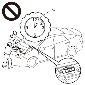
*a Without waiting for 10 minutes After removing the service plug grip, wait for at least 10 minutes before touching any of the high-voltage connectors or terminals. After waiting for 10 minutes, check the voltage at the terminals in the inspection point in the inverter with converter assembly. The voltage should be 0 V before beginning work.
Tech Tips
Waiting for at least 10 minutes is required to discharge the high-voltage capacitor inside the inverter with converter assembly.
Note
After turning the power switch off, waiting time may be required before disconnecting the cable from the negative (-) auxiliary battery terminal. Therefore, make sure to read the disconnecting the cable from the negative (-) auxiliary battery terminal notices before proceeding with work.
PROCEDURE
-
CHECK DTC OUTPUT (HYBRID CONTROL AND SOLAR CHARGING CONTROL)
-
Connect the GTS to the DLC3.
-
Turn the power switch on (IG).
-
Enter the following menus: Powertrain / Hybrid Control and Solar Charging Control / Trouble Codes.
-
Check for DTCs.
Powertrain > Hybrid Control > Trouble Codes
Powertrain > Solar Charging Control > Trouble CodesResult Result Proceed to P1ECB00 only is output, or DTCs except the ones in the table below are also output. A DTCs of hybrid control system in the tables below are output. B DTCs of solar charging system in the tables below are output. C Malfunction Content System Relevant DTC Microcomputer malfunction Hybrid control system P060647 Hybrid/EV Powertrain Control Module Processor Watchdog / Safety MCU Failure P060687 Hybrid/EV Powertrain Control Module Processor to Monitoring Processor Missing Message P060694 Hybrid/EV Powertrain Control Module Processor Unexpected Operation P060A29 Hybrid/EV Powertrain Control Module Monitoring Processor Signal Invalid P060A44 Hybrid/EV Powertrain Control Module Monitoring Processor Data Memory Failure P060A45 Hybrid/EV Powertrain Control Module Monitoring Processor Program Memory Failure P060A47 Hybrid/EV Powertrain Control Module Monitoring Processor Watchdog / Safety MCU Failure P060A49 Hybrid/EV Powertrain Control Module Monitoring Processor Internal Electronic Failure P060A87 Hybrid/EV Powertrain Control Module Processor from Monitoring Processor Missing Message P060A94 Hybrid/EV Powertrain Control Module Monitoring Processor Unexpected Operation P1EC900 Hybrid/EV Powertrain Control Module Processor or Monitoring Processor Solar Charging Permission Signal Internal Failure P1ECA00 Hybrid/EV Powertrain Control Module Processor and Monitoring Processor Solar Charging Permission Signal Stuck On Power source circuit malfunction Hybrid control system P056014 System Voltage (BATT) Circuit Short to Ground or Open P06881F ECM/PCM Power Relay Sense Circuit Intermittent Communication system malfunction Hybrid control system U113A87 Lost Communication with Solar Charging Control Module Missing Message Solar charging system U029387 Lost Communication with Hybrid/EV Powertrain Control Module Missing Message U115087 Lost Communication with Hybrid Powertrain Control Module (Hybrid/EV Battery Local Bus) Missing Message System malfunction Hybrid control system P1C9E9F Hybrid/EV System Reset Stuck Off Tech Tips
-
P1ECB00 may be output as a result of the malfunction indicated by the DTCs above.
-
The chart above is listed in inspection order of priority.
-
Check DTCs that are output at the same time by following the listed order. (The main cause of the malfunction can be determined without performing unnecessary inspections.)
-
-
Turn the power switch off.
B 
GO TO DTC CHART (HYBRID CONTROL SYSTEM) Click here
C
GO TO DTC CHART (SOLAR CHARGING SYSTEM) Click here
A 
-
-
CHECK CONNECTOR CONNECTION CONDITION (HYBRID VEHICLE CONTROL ECU CONNECTOR)
Result Result Proceed to OK A NG (The connector is not connected securely.) B NG (The terminals are not making secure contact or are deformed, or water or foreign matter exists in the connector.) C
-
Check the connection condition of the Hybrid vehicle control ECU connectors and the contact pressure of each terminal. Check the terminals for deformation, and check the connector for water ingress and foreign matter.
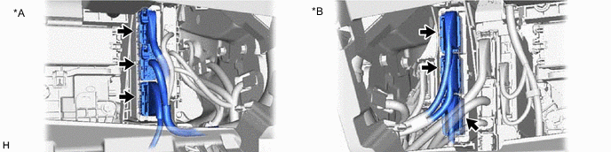
*A for LHD *B for RHD OK - The connector is connected securely. - The terminals are not deformed and are connected securely. - No water or foreign matter in the connector. Result Result Proceed to OK A NG (The connector is not connected securely.) B NG (The terminals are not making secure contact or are deformed, or water or foreign matter exists in the connector.) C
B
CONNECT SECURELY
C
REPAIR OR REPLACE HARNESS OR CONNECTOR
A
-
-
CHECK CONNECTOR CONNECTION CONDITION (SOLAR ENERGY CONTROL UNIT CONNECTOR)
Result Result Proceed to OK A NG (The connector is not connected securely.) B NG (The terminals are not making secure contact or are deformed, or water or foreign matter exists in the connector.) C CAUTION:
Be sure to wear insulated gloves.
-
Check that the service plug grip is not installed.
Note
After removing the service plug grip, do not turn the power switch on (READY), unless instructed by the repair manual because this may cause a malfunction.
-
Remove the rear seat cushion assembly LH.
-
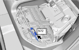
Check the connection condition of the N72 solar energy control unit connector and the contact pressure of each terminal. Check the terminals for deformation, and check the connector for water ingress and foreign matter.
OK - The connector is connected securely. - The terminals are not deformed and are connected securely. - No water or foreign matter in the connector. -
Install the rear seat cushion assembly LH.
Result Result Proceed to OK A NG (The connector is not connected securely.) B NG (The terminals are not making secure contact or are deformed, or water or foreign matter exists in the connector.) C
B
CONNECT SECURELY
C
REPAIR OR REPLACE HARNESS OR CONNECTOR
A
-
-
CHECK HARNESS AND CONNECTOR (HYBRID VEHICLE CONTROL ECU - SOLAR ENERGY CONTROL UNIT)
CAUTION:
Be sure to wear insulated gloves.
-
Check that the service plug grip is not installed.
Note
After removing the service plug grip, do not turn the power switch on (READY), unless instructed by the repair manual because this may cause a malfunction.
-
Remove the rear seat cushion assembly LH.
-
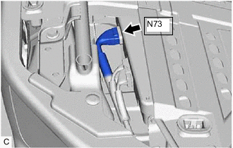
Disconnect the N73 solar energy control unit connector.
-
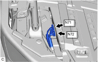
Disconnect the N71 and N72 solar energy control unit connectors.
-
Disconnect the I3 hybrid vehicle control ECU connector.
-
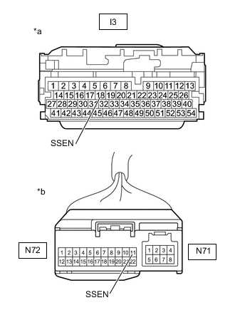
*a Front view of wire harness connector
(to Hybrid Vehicle Control ECU)
*b Front view of wire harness connector
(to Solar Energy Control Unit)
Measure the resistance according to the value(s) in the table below.
Standard Resistance Tester Connection Condition Specified Condition I3-18 (SSEN) - N72-11 (SSEN) Power switch off Below 1 Ω I3-18 (SSEN) - Body ground Power switch off 10 kΩ or higher -
Reconnect the I3 hybrid vehicle control ECU connector.
-
Reconnect the N73 solar energy control unit connector.
-
Reconnect the N71 and N72 solar energy control unit connectors.
-
Install the rear seat cushion assembly LH.
Result Proceed to OK NG
NG
REPAIR OR REPLACE HARNESS OR CONNECTOR
OK
-
-
CHECK SOLAR ENERGY CONTROL UNIT
CAUTION:
Be sure to wear insulated gloves.
-
Check that the service plug grip is not installed.
Note
After removing the service plug grip, do not turn the power switch on (READY), unless instructed by the repair manual because this may cause a malfunction.
-
Disconnect the I3 hybrid vehicle control ECU connector.
-
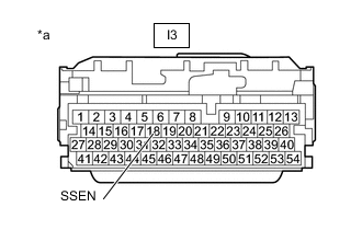
*a Front view of wire harness connector
(to Hybrid Vehicle Control ECU)
Measure the resistance according to the value(s) in the table below.
Standard Resistance Tester Connection Condition Specified Condition I3-18 (SSEN) - Body ground Power switch off 10 kΩ or higher -
Reconnect the I3 hybrid vehicle control ECU connector.
Result Proceed to OK NG
OK
REPLACE HYBRID VEHICLE CONTROL ECU Click here
NG
REPLACE SOLAR ENERGY CONTROL UNIT Click here
-