HYBRID CONTROL SYSTEM, Diagnostic DTC:P0AE415
| DTC Code | DTC Name |
|---|---|
| P0AE415 | Hybrid/EV Battery Precharge Contactor Circuit Short to Auxiliary Battery or Open |
DESCRIPTION
Refer to the description for DTC P0AE411.
| DTC No. | Detection Item | DTC Detection Condition | Trouble Area | MIL | Warning Indicate |
|---|---|---|---|---|---|
| P0AE415 | Hybrid/EV Battery Precharge Contactor Circuit Short to Auxiliary Battery or Open | Open or short to +B in SMRP circuit: Primary circuit of SMRP is malfunctioning. (2 trip detection logic) |
|
Does not come on | Master Warning Light: Comes on |
| DTC No. | Data List |
|---|---|
| P0AE415 |
|
CONFIRMATION DRIVING PATTERN
Tech Tips
After repair has been completed, clear the DTC and then check that the vehicle has returned to normal by performing the following All Readiness check procedure.
-
Connect the GTS to the DLC3.
-
Turn the power switch on (IG) and turn the GTS on.
-
Clear the DTCs (even if no DTCs are stored, perform the clear DTC procedure).
-
Turn the power switch off and wait for 2 minutes or more.
-
Turn the power switch on (READY) and wait for 30 seconds or more.
-
Turn the power switch off and wait for 2 minutes or more.
-
Turn the power switch on (IG) and turn the GTS on.
-
Enter the following menus: Powertrain / Hybrid Control / Utility / All Readiness.
-
Check the DTC judgment result.
Tech Tips
-
If the judgment result shows NORMAL, the system is normal.
-
If the judgment result shows ABNORMAL, the system has a malfunction.
-
If the judgment result shows INCOMPLETE or N/A, perform driving pattern again.
-
CAUTION / NOTICE / HINT
CAUTION:
-

Before the following operations are conducted, take precautions to prevent electric shock by turning the power switch off, wearing insulated gloves, and removing the service plug grip from HV battery.
-
Inspecting the high-voltage system
-
Disconnecting the low voltage connector of the inverter with converter assembly
-
Disconnecting the low voltage connector of the HV battery
-
Disconnecting the low voltage connector of the electric vehicle charger assembly.
-
Disconnecting the low voltage connector of the solar energy control unit
-

To prevent electric shock, make sure to remove the service plug grip to cut off the high voltage circuit before servicing the vehicle.
-

After removing the service plug grip from the HV battery, put it in your pocket to prevent other technicians from accidentally reconnecting it while you are working on the high-voltage system.
-
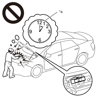
*a Without waiting for 10 minutes After removing the service plug grip, wait for at least 10 minutes before touching any of the high-voltage connectors or terminals. After waiting for 10 minutes, check the voltage at the terminals in the inspection point in the inverter with converter assembly. The voltage should be 0 V before beginning work.
Tech Tips
Waiting for at least 10 minutes is required to discharge the high-voltage capacitor inside the inverter with converter assembly.
Note
After turning the power switch off, waiting time may be required before disconnecting the cable from the negative (-) auxiliary battery terminal. Therefore, make sure to read the disconnecting the cable from the negative (-) auxiliary battery terminal notices before proceeding with work.
Tech Tips
If DTC P0AE415 is output, the power switch cannot be turned on (READY).
PROCEDURE
-
READ VALUE USING GTS (SMRP STATUS)
-
Connect the GTS to the DLC3
-
Turn the power switch on (IG).
-
Enter the following menus: Powertrain / Hybrid Control / Data List / SMRP Status.
Powertrain > Hybrid Control > Data ListTester Display SMRP Status -
Read the Data List.
Standard Tester Display Condition Specified Condition SMRP Status Power switch on (IG) OFF -
Turn the power switch off.
Result Proceed to OK NG
NG 
CHECK HARNESS AND CONNECTOR (SMRP VOLTAGE) Click here
OK 
-
-
CHECK CONNECTOR CONNECTION CONDITION (HYBRID VEHICLE CONTROL ECU CONNECTOR)
Result Proceed to OK NG
-
Check the connector connections and contact pressure of the relevant terminals for the hybrid vehicle control ECU connectors.
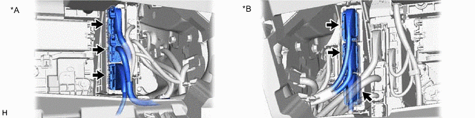
*A for LHD *B for RHD OK The connectors are connected securely and there are no contact pressure problems. Result Proceed to OK NG
NG 
CONNECT SECURELY
OK
-
-
CHECK CONNECTOR CONNECTION CONDITION (FLOOR WIRE CONNECTOR)
Result Result Proceed to OK A NG (The connector is not connected securely.) B NG (The terminals are not making secure contact or are deformed, or water or foreign matter exists in the connector.) C
-
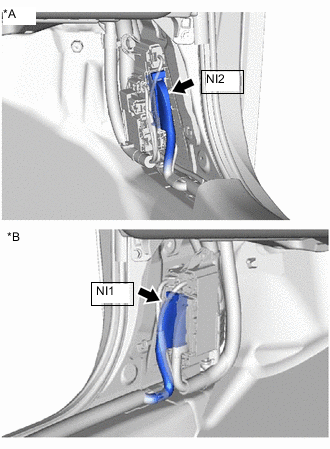
*A for LHD *B for RHD Check the connection condition of theNI2 or NI1 floor wire connector and the contact pressure of each terminal. Check the terminals for deformation, and check the connector for water ingress and foreign matter.
OK - The connector is connected securely. - The terminals are not deformed and are connected securely. - No water or foreign matter in the connector. Result Result Proceed to OK A NG (The connector is not connected securely.) B NG (The terminals are not making secure contact or are deformed, or water or foreign matter exists in the connector.) C
B
CONNECT SECURELY
C
REPAIR OR REPLACE HARNESS OR CONNECTOR
A
-
-
CHECK CONNECTOR CONNECTION CONDITION (NO. 1 HYBRID BATTERY PACK WIRE CONNECTOR)
Result Result Proceed to OK A NG (The connector is not connected securely.) B NG (The terminals are not making secure contact or are deformed, or water or foreign matter exists in the connector.) C
-
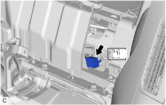
*1 Nt1 Check the connection condition of the Nt1 No. 1 hybrid battery pack wire connector and the contact pressure of each terminal. Check the terminals for deformation, and check the connector for water ingress and foreign matter.
OK - The connector is connected securely. - The terminals are not deformed and are connected securely. - No water or foreign matter in the connector. Result Result Proceed to OK A NG (The connector is not connected securely.) B NG (The terminals are not making secure contact or are deformed, or water or foreign matter exists in the connector.) C
B
CONNECT SECURELY
C
REPAIR OR REPLACE HARNESS OR CONNECTOR
A
-
-
CHECK CONNECTOR CONNECTION CONDITION (NO. 1 HV BATTERY JUNCTION BLOCK ASSEMBLY CONNECTOR)
Result Proceed to OK NG CAUTION:
Be sure to wear insulated gloves and protective goggles.
-
Check that the service plug grip is not installed.
Note
After removing the service plug grip, do not turn the power switch on (IG), unless instructed by the repair manual because this may cause a malfunction.
-
Remove the upper hybrid battery cover sub-assembly.
-
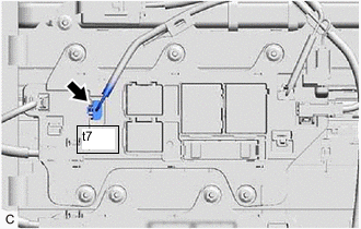
Check the connector connections and contact pressure of the relevant terminals of the t7 No. 1 HV battery junction block assembly connector.
OK The connectors are connected securely and there are no contact pressure problems. -
Install the upper hybrid battery cover sub-assembly.
Result Proceed to OK NG
OK
CHECK FOR INTERMITTENT PROBLEMS Click here
NG
CONNECT SECURELY
-
-
CHECK HARNESS AND CONNECTOR (SMRP VOLTAGE)
-
Turn the power switch on (IG).
-
Measure the voltage according to the value(s) in the table below.
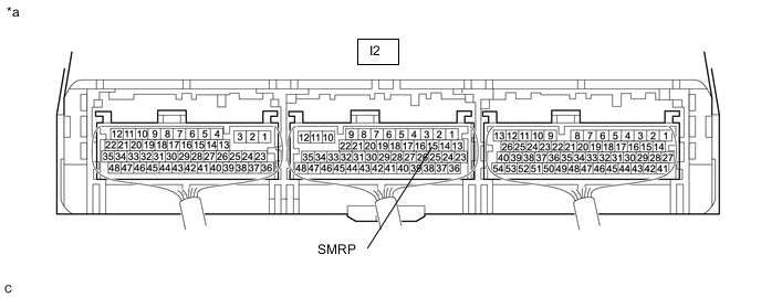
*a Component with harness connected
(Hybrid Vehicle Control ECU)
- - Standard Voltage Tester Connection Condition Specified Condition I2-15 (SMRP) - Body ground Power switch on (IG) Below 1 V -
Turn the power switch off.
Result Proceed to OK NG
NG
CHECK HARNESS AND CONNECTOR (HYBRID VEHICLE CONTROL ECU - BODY GROUND) Click here
OK
-
-
CHECK CONNECTOR CONNECTION CONDITION (HYBRID VEHICLE CONTROL ECU CONNECTOR)
Result Proceed to OK NG
-
Check the connector connections and contact pressure of the relevant terminals for the hybrid vehicle control ECU connectors.
*A for LHD *B for RHD OK The connectors are connected securely and there are no contact pressure problems. Result Proceed to OK NG
OK
REPLACE HYBRID VEHICLE CONTROL ECU Click here
NG
CONNECT SECURELY
-
-
CHECK HARNESS AND CONNECTOR (HYBRID VEHICLE CONTROL ECU - BODY GROUND)
-
Disconnect the I2 hybrid vehicle control ECU connector.
-
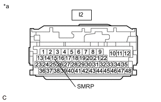
*a Front view of wire harness connector
(to Hybrid Vehicle Control ECU)
Measure the resistance according to the value(s) in the table below.
Standard Resistance Tester Connection Condition Specified Condition I2-15 (SMRP) - Body ground Power switch off 140 to 290 Ω -
Reconnect the I2 hybrid vehicle control ECU connector.
Result Proceed to OK NG
NG
CHECK CONNECTOR CONNECTION CONDITION (FLOOR WIRE CONNECTOR) Click here
OK
-
-
CHECK HARNESS AND CONNECTOR (SHORT TO POWER SUPPLY WIRES)
CAUTION:
Be sure to wear insulated gloves and protective goggles.
-
Check that the service plug grip is not installed.
Note
After removing the service plug grip, do not turn the power switch on (READY), unless instructed by the repair manual because this may cause a malfunction.
-
Remove the upper hybrid battery cover sub-assembly.
-
Disconnect the t7 No. 1 HV battery junction block assembly.
-
Disconnect the I2 hybrid vehicle control ECU connector.
-
Turn the power switch on (IG).
-
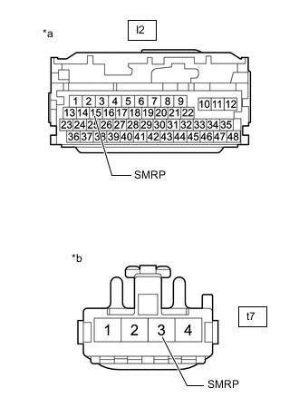
*a Front view of wire harness connector
(to Hybrid Vehicle Control ECU)
*b Front view of wire harness connector
(to No. 1 HV Battery Junction Block Assembly)
Measure the voltage according to the value(s) in the table below.
Standard Voltage Tester Connection Condition Specified Condition I2-15 (SMRP) and t7-3 (SMRP) - Body ground and other terminals Power switch on (IG) Below 1 V Note
Turning the power switch on (IG) with the hybrid vehicle control ECU connector and the No. 1 HV battery junction block assembly connector disconnected causes other DTCs to be stored. Clear the DTCs after performing this inspection.
-
Turn the power switch off.
-
Reconnect the I2 hybrid vehicle control ECU connector.
-
Reconnect the t7 No. 1 HV battery junction block assembly.
-
Install the upper hybrid battery cover sub-assembly.
Result Proceed to OK NG
OK
REPLACE HYBRID VEHICLE CONTROL ECU Click here
NG
REPAIR OR REPLACE HARNESS OR CONNECTOR
-
-
CHECK CONNECTOR CONNECTION CONDITION (FLOOR WIRE CONNECTOR)
Result Result Proceed to OK A NG (The connector is not connected securely.) B NG (The terminals are not making secure contact or are deformed, or water or foreign matter exists in the connector.) C
-
*A for LHD *B for RHD Check the connection condition of theNI2 or NI1 floor wire connector and the contact pressure of each terminal. Check the terminals for deformation, and check the connector for water ingress and foreign matter.
OK - The connector is connected securely. - The terminals are not deformed and are connected securely. - No water or foreign matter in the connector. Result Result Proceed to OK A NG (The connector is not connected securely.) B NG (The terminals are not making secure contact or are deformed, or water or foreign matter exists in the connector.) C
B
CONNECT SECURELY
C
REPAIR OR REPLACE HARNESS OR CONNECTOR
A
-
-
CHECK CONNECTOR CONNECTION CONDITION (NO. 1 HYBRID BATTERY PACK WIRE CONNECTOR)
Result Result Proceed to OK A NG (The connector is not connected securely.) B NG (The terminals are not making secure contact or are deformed, or water or foreign matter exists in the connector.) C
-
*1 Nt1 Check the connection condition of the Nt1 No. 1 hybrid battery pack wire connector and the contact pressure of each terminal. Check the terminals for deformation, and check the connector for water ingress and foreign matter.
OK - The connector is connected securely. - The terminals are not deformed and are connected securely. - No water or foreign matter in the connector. Result Result Proceed to OK A NG (The connector is not connected securely.) B NG (The terminals are not making secure contact or are deformed, or water or foreign matter exists in the connector.) C
B
CONNECT SECURELY
C
REPAIR OR REPLACE HARNESS OR CONNECTOR
A
-
-
CHECK HARNESS AND CONNECTOR (HYBRID VEHICLE CONTROL ECU - NO. 1 HV BATTERY JUNCTION BLOCK ASSEMBLY)
CAUTION:
Be sure to wear insulated gloves and protective goggles.
-
Check that the service plug grip is not installed.
Note
After removing the service plug grip, do not turn the power switch on (READY), unless instructed by the repair manual because this may cause a malfunction.
-
Remove the upper hybrid battery cover sub-assembly.
-
Disconnect the t7 No. 1 HV battery junction block assembly connector.
-
Disconnect the I2 hybrid vehicle control ECU connector.
-
*a Front view of wire harness connector
(to Hybrid Vehicle Control ECU)
*b Front view of wire harness connector
(to No. 1 HV Battery Junction Block Assembly)
Measure the resistance according to the value(s) in the table below.
Standard Resistance (Check for Open) Tester Connection Condition Specified Condition I2-15 (SMRP) - t7-3 (SMRP) Power switch off Below 1 Ω Standard Resistance (Check for Short) Tester Connection Condition Specified Condition I2-15 (SMRP) and t7-3 (SMRP) - Body ground and other terminals Power switch off 10 kΩ or higher -
Reconnect the I2 hybrid vehicle control ECU connector.
-
Reconnect the t7 No. 1 HV battery junction block assembly connector.
-
Install the upper hybrid battery cover sub-assembly.
Result Proceed to OK NG
NG
REPAIR OR REPLACE HARNESS OR CONNECTOR
OK
-
-
CHECK HARNESS AND CONNECTOR (NO. 1 HV BATTERY JUNCTION BLOCK ASSEMBLY - BODY GROUND)
Result Proceed to OK NG CAUTION:
Be sure to wear insulated gloves and protective goggles.
-
Check that the service plug grip is not installed.
Note
After removing the service plug grip, do not turn the power switch on (IG), unless instructed by the repair manual because this may cause a malfunction.
-
Remove the upper hybrid battery cover sub-assembly.
-
Disconnect the t7 No. 1 HV battery junction block assembly connector.
-
*a Front view of wire harness connector
(to No. 1 HV Battery Junction Block Assembly)
Measure the resistance according to the value(s) in the table below.
Standard Resistance Tester Connection Condition Specified Condition t7-2 (GND1) - Body ground Power switch off Below 1 Ω -
Reconnect the t7 No. 1 HV battery junction block assembly connector.
-
Install the upper hybrid battery cover sub-assembly.
Result Proceed to OK NG
NG
REPAIR OR REPLACE HARNESS OR CONNECTOR
OK
-
-
INSPECT NO. 1 HV BATTERY JUNCTION BLOCK ASSEMBLY (SMRP)
CAUTION:
Be sure to wear insulated gloves and protective goggles.
-
Check that the service plug grip is not installed.
Note
After removing the service plug grip, do not turn the power switch on (READY), unless instructed by the repair manual because this may cause a malfunction.
-
Remove the upper hybrid battery cover sub-assembly.
-
Disconnect the t7 No. 1 HV battery junction block assembly connector.
-
Measure the resistance according to the value(s) in the table below.
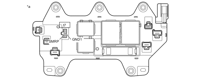
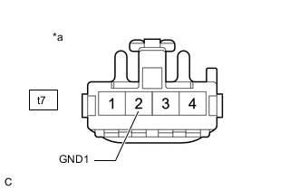
*a Component without harness connected
(No. 1 HV Battery Junction Block Assembly)
- - Standard Resistance Tester Connection Condition Specified Condition t7-3 (SMRP) - t7-2 (GND1) -40 to 80°C (-40 to 176°F) 140 to 290 Ω -
Reconnect the t7 No. 1 HV battery junction block assembly connector.
-
Install the upper hybrid battery cover sub-assembly.
Result Proceed to OK NG
OK
CHECK FOR INTERMITTENT PROBLEMS Click here
NG
REPLACE NO. 1 HV BATTERY JUNCTION BLOCK ASSEMBLY Click here
-