HYBRID CONTROL SYSTEM, Diagnostic DTC:P0AA649, P1C7C49, P1C7D49, P1C7E49, P1C7F49, P1CF749, P33CF49
| DTC Code | DTC Name |
|---|---|
| P0AA649 | Hybrid/EV Battery Voltage System Isolation Internal Electronic Failure |
| P1C7C49 | Hybrid/EV Battery Voltage System Isolation (A/C Area) Internal Electronic Failure |
| P1C7D49 | Hybrid/EV Battery Voltage System Isolation (Hybrid/EV Battery Area) Internal Electronic Failure |
| P1C7E49 | Hybrid/EV Battery Voltage System Isolation (Transaxle Area) Internal Electronic Failure |
| P1C7F49 | Hybrid/EV Battery Voltage System Isolation (Direct Current Area) Internal Electronic Failure |
| P1CF749 | Hybrid/EV Battery Voltage System Isolation (Charger Area) Internal Electronic Failure |
| P33CF49 | Hybrid/EV Battery Voltage System Isolation Internal Electronic Failure Abnormal Area Detection Failure |
DESCRIPTION
The hybrid vehicle control ECU monitors the battery ECU assembly and detects insulation malfunctions in the high-voltage system.
| DTC No. | Detection Item | DTC Detection Condition | Trouble Area | MIL | Warning Indicate |
|---|---|---|---|---|---|
| P0AA649 | Hybrid/EV Battery Voltage System Isolation Internal Electronic Failure | Insulation resistance between the high-voltage circuit and the body has decreased.*2 (1 trip detection logic) |
|
Does not come on | Master Warning Light: Comes on |
| P1C7C49 | Hybrid/EV Battery Voltage System Isolation (A/C Area) Internal Electronic Failure | Insulation resistance of the compressor with motor assembly or air conditioning inverter has decreased.*3 (1 trip detection logic) |
Air conditioning system | Does not come on | Master Warning Light: Comes on |
| P1C7D49 | Hybrid/EV Battery Voltage System Isolation (Hybrid/EV Battery Area) Internal Electronic Failure | Insulation resistance of the HV battery, battery ECU assembly or SMR has decreased.*3 (1 trip detection logic) |
|
Comes on | Master Warning Light: Comes on |
| P1C7E49 | Hybrid/EV Battery Voltage System Isolation (Transaxle Area) Internal Electronic Failure | Insulation resistance of the hybrid vehicle transaxle assembly or inverter for the generator (MG1) and motor (MG2) has decreased.*3 (1 trip detection logic) |
|
Does not come on | Master Warning Light: Comes on |
| P1C7F49 | Hybrid/EV Battery Voltage System Isolation (Direct Current Area) Internal Electronic Failure | Insulation resistance of the inverter for the generator (MG1) and motor (MG2), A/C inverter, SMR or No. 2 engine room wire has decreased.*3 (1 trip detection logic) |
|
Does not come on | Master Warning Light: Comes on |
| P1CF749 | Hybrid/EV Battery Voltage System Isolation (Charger Area) Internal Electronic Failure | Insulation resistance of the electric vehicle charger assembly, solar energy control unit, SMR, or DC charge high-voltage wire harness has decreased.*3 (1 trip detection logic) |
|
Comes on | Master Warning Light: Comes on |
| P33CF49 | Hybrid/EV Battery Voltage System Isolation Internal Electronic Failure Abnormal Area Detection Failure | Insulation resistance has decreased in an unspecified area. (1 trip detection logic) |
|
Comes on | Master Warning Light: Comes on |
*1: w/ Solar Charging System
Tech Tips
-
*2: The insulation malfunction detection circuit in the battery ECU assembly monitors the insulation resistance between the high voltage circuits and body. If the insulation resistance decreases, the hybrid vehicle control ECU stores DTC P0AA649 and illuminates the master warning light first regardless of malfunction area.
Depending on the vehicle condition, the high voltage circuit insulation resistance may return to normal. So if DTC P0AA649 outputs, complete the following steps as soon as possible.
-
*3: If the following operations are performed within the same trip after DTC P0AA649 is stored, just one of the related DTCs (P1C7C49, P1C7D49, P1C7E49, P1C7F49 or P1CF749) will be stored.
-
Apply the parking brake firmly.
-
Wait for 1 minute or more with the vehicle stopped, the brake pedal firmly depressed, the power switch on (READY), drive (D) selected and the air conditioning system on (Lo/MAX COOL, blower speed HI).
-
Turn the power switch off and wait for 2 minutes or more.
-
Connect the electric vehicle charger cable assembly, and plug-in charge the vehicle for 3 minutes or more.
Tech Tips
-
DTCs and freeze frame data are useful information in determining the malfunctioning part. Before performing diagnosis, make sure to check and make a note of all output DTCs and freeze frame data. (Even if a high-voltage insulation malfunction cannot be reproduced, once stored, DTCs of insulation will not be cleared unless the clear operation is performed.)
-
When the insulation resistance of the HV battery area decreases and the power switch is turned on (IG), DTC P1C7D49 is stored within 2 minutes.
-
-
When measuring insulation resistance using a megohmmeter, measure the resistance while jiggling the high voltage wire harness.
| DTC No. | Data List |
|---|---|
| P0AA649 |
|
| P1C7C49 | |
| P1C7D49 | |
| P1C7E49 | |
| P1C7F49 | |
| P1CF749 | |
| P33CF49 |
Use the following items as a reference when duplicating the vehicle conditions at the time when the malfunction occurred.
-
Vehicle Speed
-
Engine Run Time
-
BATT Voltage
-
Distance from DTC Cleared
-
Ready Signal
-
Hybrid Battery SOC
Data List
CONFIRMATION DRIVING PATTERN
-
CONFIRMATION AFTER REPLACING PARTS
Tech Tips
After repair has been completed, clear the DTC and then check that the vehicle has returned to normal by performing the following All Readiness check procedure. (Do not turn the power switch off (READY off) during this inspection.)
-
Connect the GTS to the DLC3.
-
Turn the power switch on (IG) and turn the GTS on.
-
Clear the DTCs (even if no DTCs are stored, perform the clear DTC procedure).
-
Turn the power switch off and wait for 2 minutes or more.
-
Apply the parking brake and secure the wheels using chocks.
-
When the vehicle is stationary, turn the power switch on (READY) with park (P) selected and wait for1 minute or more.
-
Turn the air conditioning system on (MAX COLD, blower speed HI).
-
While depressing the brake pedal without depressing the accelerator pedal, move the shift lever to D and wait for 5 minutes.
- If step B is performed within the same trip after DTC P0AA649 is stored, the parts with insufficient insulation resistance will be determined and a DTC (P1C7C49, P1C7D49, P1C7E49 or P1C7F49) will be stored.
- If no DTCs are output, proceed to the step A.
-
Drive the vehicle for approximately 5 minutes referring to the following freeze frame data items: "Vehicle Speed", "Shift Position", "Accelerator Position Sensor No.1 Voltage %", "Engine Speed", "Coolant Temperature", "Master Cylinder Control Torque", "Motor Temperature" and "Generator Temperature". (Step A)
(If the freeze frame data item "Vehicle Speed" is 10 km/h (6 mph) or less, drive the vehicle at 10km/h (6 mph) or more.)
- If step B is performed within the same trip after DTC P0AA649 is stored, the parts with insufficient insulation resistance will be determined and a DTC (P1C7C49, P1C7D49, P1C7E49 or P1C7F49) will be stored.
- If DTC P0AA649 is output, complete the Step B immediately as quickly as possible.
- If no DTCs are output, proceed to the step C.
-
Wait for 1 minute or more with the vehicle stopped, the power switch on (READY), park (P) selected and the air conditioning system on (Lo/COOL MAX, blower speed HI), then turn the power switch off and wait for 2 minutes or more. (Step B)
-
Turn the power switch off and connect the electric vehicle charger cable assembly, and plug-in charge the vehicle for 3 minutes or more. (step C)
- When charging does not continue for 3 minutes with no DTC output, lower the SOC and then perform the step C again.
- If DTC P0AA649 is output at this step, the area where the insulation resistance has decreased is specified and DTC P1C7D49, P1CF749 or P33CF49 is also output.
-
Turn the power switch on (IG) and turn the GTS on.
-
Enter the following menus: Powertrain / Hybrid Control / Utility / All Readiness.
-
Check the DTC judgment result.
Tech Tips
-
If the judgment result shows NORMAL, the system is normal.
-
If the judgment result shows ABNORMAL, the system has a malfunction.
-
If the judgment result shows INCOMPLETE or N/A, perform driving pattern again.
-
-
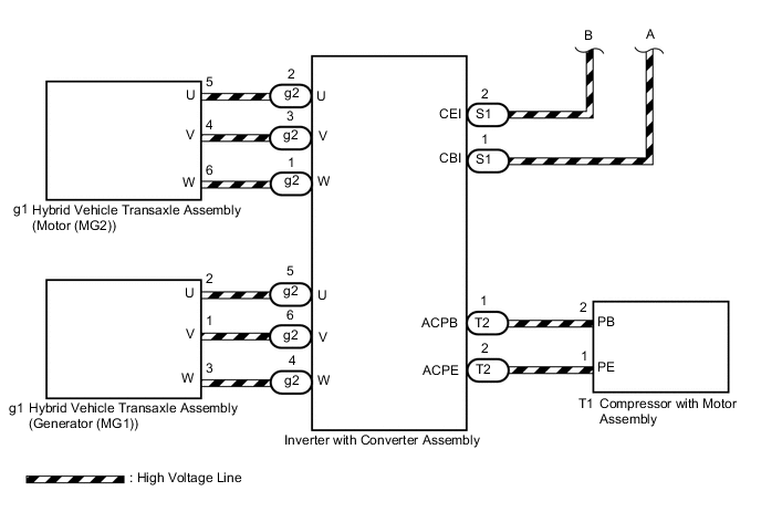
WIRING DIAGRAM
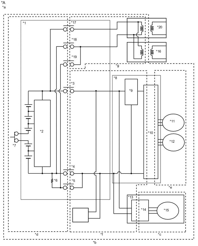
| *A | w/ Solar Charging System | - | - |
| *1 | HV Battery | *2 | Battery ECU assembly |
| *3 | SMRB | *4 | SMRG |
| *5 | SMRP | *6 | System Main Resistor |
| *7 | Service Plug Grip | *8 | Inverter with Converter Assembly |
| *9 | Boost Converter | *10 | Inverter |
| *11 | Generator (MG1) | *12 | Motor (MG2) |
| *13 | Compressor with Motor Assembly | *14 | A/C Inverter |
| *15 | A/C Motor | *16 | Electric Vehicle Charger Assembly |
| *17 | CHRB | *18 | CHRG |
| *19 | CHRP | *20 | Solar Energy Control Unit |
| *a | High-voltage Areas | *b | DTC P0AA649 Vehicle Insulation Resistance Reduction Area |
| *c | DTC P1C7C49 Air Conditioning System Area | *d | DTC P1C7D49 HV Battery Area |
| *e | DTC P1C7E49 Hybrid Vehicle Transaxle Assembly Area | *f | DTC P1C7F49 High Voltage Direct Current Area |
| *g | DTC P1CF749 Charger Area | - | - |
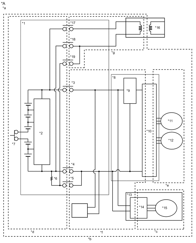
| *A | w/o Solar Charging System | - | - |
| *1 | HV Battery | *2 | Battery ECU assembly |
| *3 | SMRB | *4 | SMRG |
| *5 | SMRP | *6 | System Main Resistor |
| *7 | Service Plug Grip | *8 | Inverter with Converter Assembly |
| *9 | Boost Converter | *10 | Inverter |
| *11 | Generator (MG1) | *12 | Motor (MG2) |
| *13 | Compressor with Motor Assembly | *14 | A/C Inverter |
| *15 | A/C Motor | *16 | Electric Vehicle Charger Assembly |
| *17 | CHRB | *18 | CHRG |
| *19 | CHRP | - | - |
| *a | High-voltage Areas | *b | DTC P0AA649 Vehicle Insulation Resistance Reduction Area |
| *c | DTC P1C7C49 Air Conditioning System Area | *d | DTC P1C7D49 HV Battery Area |
| *e | DTC P1C7E49 Hybrid Vehicle Transaxle Assembly Area | *f | DTC P1C7F49 High Voltage Direct Current Area |
| *g | DTC P1CF749 Charger Area | - | - |
SYSTEM DESCRIPTION
Tech Tips
If a decrease in insulation resistance cannot be confirmed using a megohmmeter, check "Short Wave Highest Value Level" in the Data List.
-
SHORT WAVE HIGHEST VALUE LEVEL
-
"Short Wave Highest Value Level" shows a decrease in insulation resistance. When insulation resistance decreases, "Insulation Lower" will be displayed. However, even though the insulation resistance of the vehicle is normal, "Short Wave Highest Value Level" may decrease, so that "Not Judge" will be displayed for any of the following conditions.
-
Within approximately 1 minute since the power switch was turned on (IG).
-
When the system voltages ("Hybrid Battery Voltage", "VL-Voltage before Boosting" and "VH-Voltage after Boosting") are changing.
-
During boosting. If the Data List item "Boost Ratio" is not 0% or within a few seconds of it becoming 0%. (The values of "Hybrid Battery Voltage", "VL-Voltage before Boosting" and "VH-Voltage after Boosting" are about the same when not boosting.)
-
When "No" is displayed for any of the following Data List items:
- Short Wave Highest Value Availability just after MG Inv On/Off
- Short Wave Highest Value Availability just after A/C Inv On/Off
- Short Wave Highest Value Availability just after SMR On/Off
- Short Wave Highest Value Availability just after AC Charging Relay On/Off
-
-
When "Short Wave Highest Value Level" shows "Insulation Lower LV3", insulation resistance will be close to 0 Ω. In this case, damage to a high-voltage cable or hybrid component (high-voltage), or a short to body ground due to intrusion of foreign matter, such as metal particles, can be suspected.
-
-
-
If problem symptoms cannot be reproduced and a malfunction still exists after replacing a part as instructed, checking the following freeze frame data can help determine a trouble area.
Items to be Checked Using Freeze Frame Data: Freeze Frame Data Diagnostic Note Short Wave Highest Value Level Indicates that the insulation resistance has decreased.
-
VL-Voltage before Boosting
-
VH-Voltage after Boosting
-
Hybrid Battery Voltage
-
Boost Ratio
During boosting (when "Boost Ratio" is not 0%), or when "VL-Voltage before Boosting", "VH-Voltage after Boosting" or "Hybrid Battery Voltage" is varying, "Short Wave Highest Value Level" may decrease even though the insulation resistance is normal.
-
SMRP Status
-
SMRB Status
-
SMRG Status
-
AC Charging Precharge Relay Status
-
AC Charging Positive Relay Status
-
AC Charging Negative Relay Status
When "SMRP Status", "SMRB Status", "SMRG Status", "CHRP Status", "CHRB Status" and "CHRG Status" are all OFF, the insulation malfunction detection circuit detects a decrease in insulation resistance in the HV battery area ((*d) in the wiring diagram).
-
When the power switch is turned on (IG) (not on (READY)) and the electric vehicle charger cable assembly is disconnected, and the solar charging system is not operating, all 3 system main relays and 3 charge relays are off and it is suspected that the HV battery is disconnected from the high voltage circuits.
If "Insulation Short Wave Highest Value Level" decreases a few minutes after the power switch is turned on (IG) (not on (READY)) and the electric vehicle charger cable assembly is disconnected, the HV battery may have an insulation malfunction.
Example:
Motor Inverter Shutdown Status When "Motor Inverter Shutdown Status" is ON, the insulation malfunction detection circuit cannot detect a decrease in insulation resistance in the motor system AC (alternating current) section (motor (MG2) side of (*e) in the wiring diagram).
The motor system AC (alternating current) section includes the motor (MG2) in the hybrid vehicle transaxle assembly, motor cables and the AC (alternating current) section of the motor drive circuit in the inverter with converter assembly.
Generator Inverter Shutdown Status When "Generator Inverter Shutdown Status" is ON, the insulation malfunction detection circuit cannot detect a decrease in insulation resistance in the generator system AC (alternating current) section (generator (MG1) side of (*e) in the wiring diagram).
The generator system AC (alternating current) section includes the generator (MG1) in the hybrid vehicle transaxle assembly, generator cables and the AC (alternating current) section of the generator drive circuit in the inverter with converter assembly.
A/C Consumption Power The compressor with motor assembly AC (alternating current) section ((*c) in the wiring diagram) includes the air conditioning motor, wiring between the air conditioning motor and air conditioning inverter, and the AC (alternating current) section of the air conditioning motor drive circuit in the air conditioning inverter.
With the vehicle stopped, turn on/off the air conditioning system and observe "Short Wave Highest Value Level" to use as a diagnosis reference.
RELATED FREEZE FRAME DATA
Tech Tips
-
Reproducing the vehicle conditions the moment a DTC was stored according to the freeze frame data and results of the customer problem analysis helps ensure that the same DTC is stored again.
Driving Status Item Diagnostic Note Vehicle Speed - Accelerator Position Sensor No.1 Voltage % - Engine Speed - Shift Position - Master Cylinder Control Torque - Coolant Temperature - Operation Conditions Item Diagnostic Note Motor Temperature If any liquid leaks into the ATF, insulation resistance may decrease only when the temperature is high.
The motor temperature is likely to increase if the motor speed is low and output torque is high such as when cruising uphill slowly or accelerating from a low speed.
Generator Temperature If any liquid leaks into the ATF, insulation resistance may decrease only when the temperature is high.
The generator temperature is likely to increase under repeat acceleration and deceleration while the vehicle is driven in the mid speed range (60 to 80 km/h (37 to 50 mph)).
-
Customer Problem Analysis
Ask the customer about the operating conditions and environment when the malfunction occurred.
Item Diagnostic Note Driving Condition (acceleration, deceleration, turning, etc.) Changes in the insulation of the parts with insufficient insulation due to changes in G force or vibration is suspected. Road Condition (unpaved, etc.) Weather (rain, snow, etc.) Water intrusion is suspected Washing the vehicle (Whether the malfunction occurred after washing the vehicle?)
-
CAUTION / NOTICE / HINT
CAUTION:
-
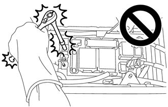
When troubleshooting DTC P0AA649, use either a tool wrapped with vinyl insulation tape or an insulated tool. (It is extremely dangerous when a high-voltage charge passes through a non-insulated tool causing a short.)
-

Before the following operations are conducted, take precautions to prevent electric shock by turning the power switch off, wearing insulated gloves, and removing the service plug grip from HV battery.
-
Inspecting the high-voltage system
-
Disconnecting the low voltage connector of the inverter with converter assembly
-
Disconnecting the low voltage connector of the HV battery
-
Disconnecting the low voltage connector of the electric vehicle charger assembly.
-
Disconnecting the low voltage connector of the solar energy control unit
-

To prevent electric shock, make sure to remove the service plug grip to cut off the high voltage circuit before servicing the vehicle.
-

After removing the service plug grip from the HV battery, put it in your pocket to prevent other technicians from accidentally reconnecting it while you are working on the high-voltage system.
-
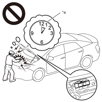
*a Without waiting for 10 minutes After removing the service plug grip, wait for at least 10 minutes before touching any of the high-voltage connectors or terminals. After waiting for 10 minutes, check the voltage at the terminals in the inspection point in the inverter with converter assembly. The voltage should be 0 V before beginning work.
Tech Tips
Waiting for at least 10 minutes is required to discharge the high-voltage capacitor inside the inverter with converter assembly.
-
Make sure to insulate the high-voltage connectors and terminals of the HV battery with insulating tape after removing it.
If the HV battery stored without insulating the connectors and terminals, electric shock or fire may result.
-
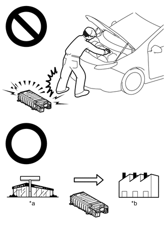
*a Dealer *b Battery Collection Agent When disposing of an HV battery, make sure to return it through an authorized collection agent who is capable of handling it safely. If the HV battery is returned via the manufacturer specified route, it will be returned properly and in a safe manner by an authorized collection agent.
-
Before returning the HV battery, make sure to perform a recovery inspection.
-
Before returning the HV supply stack sub-assembly, make sure to perform a recovery inspection.
-
Make a note of the output DTCs as some of them may be necessary for recovery inspection of the HV battery and HV supply stack sub-assemblies.
-
After removing the HV battery, keep it away from water. Exposure to water may cause the HV battery to produce heat, resulting in a fire.
Note
After turning the power switch off, waiting time may be required before disconnecting the cable from the negative (-) auxiliary battery terminal. Therefore, make sure to read the disconnecting the cable from the negative (-) auxiliary battery terminal notices before proceeding with work.
Tech Tips
When measuring insulation resistance using a megohmmeter, set the megohmmeter to 500 V.
PROCEDURE
-
CHECK DTC OUTPUT (HYBRID CONTROL, HV BATTERY)
-
Connect the GTS to the DLC3.
-
Turn the power switch on (IG).
-
Enter the following menus: Powertrain / Hybrid Control and HV Battery / Trouble Codes.
-
Check for DTCs.
Powertrain > Hybrid Control > Trouble Codes
Powertrain > HV Battery > Trouble CodesResult Result Proceed to P0AA649, P1C7C49, P1C7D49, P1C7E49 or P1C7F49 only is output, or DTCs except the ones in the table below are also output. A DTCs of hybrid control system in the tables below are output. B DTCs of hybrid battery system in the tables below are output. C Malfunction Content System Relevant DTC Microcomputer malfunction Hybrid control system P060647 Hybrid/EV Powertrain Control Module Processor Watchdog / Safety MCU Failure P060A29 Hybrid/EV Powertrain Control Module Monitoring Processor Signal Invalid P060A44 Hybrid/EV Powertrain Control Module Monitoring Processor Data Memory Failure P060A45 Hybrid/EV Powertrain Control Module Monitoring Processor Program Memory Failure P060A49 Hybrid/EV Powertrain Control Module Monitoring Processor Internal Electronic Failure P060B1C Hybrid/EV Powertrain Control Module A/D Processing Voltage Out of Range P060B71 Hybrid/EV Powertrain Control Module A/D Processing Actuator Stuck P1CE31C Hybrid/EV Powertrain Control Module Monitoring Processor A/D Processing Voltage Out of Range P1CE349 Hybrid/EV Powertrain Control Module Monitoring Processor A/D Processing Internal Electronic Failure P1CE371 Hybrid/EV Powertrain Control Module Monitoring Processor A/D Processing Actuator Stuck Hybrid battery system P060687 Hybrid/EV Battery Energy Control Module Processor to Monitoring Processor Missing Message P060A47 Hybrid/EV Battery Energy Control Module Monitoring Processor Watchdog / Safety MCU Failure P060A87 Hybrid/EV Battery Energy Control Module Processor from Monitoring Processor Missing Message P060B49 Hybrid/EV Powertrain Control Module A/D Processing Internal Electronic Failure P062F46 Hybrid/EV Battery Energy Control Module EEPROM Calibration / Parameter Memory Failure Power Source Circuit Malfunction Hybrid control system P06881F ECM/PCM Power Relay Sense Circuit Intermittent System malfunction Hybrid control system P1C9E9F Hybrid/EV System Reset Stuck Off Tech Tips
-
P0AA649 may be output as a result of the malfunction indicated by the DTCs above.
-
The chart above is listed in inspection order of priority.
-
Check DTCs that are output at the same time by following the listed order. (The main cause of the malfunction can be determined without performing unnecessary inspections.)
-
-
Turn the power switch off.
B 
GO TO DTC CHART (HYBRID CONTROL SYSTEM) Click here
C
GO TO DTC CHART (HYBRID BATTERY SYSTEM) Click here
A 
-
-
CHECK DTC OUTPUT (HYBRID CONTROL)
-
Connect the GTS to the DLC3.
-
Turn the power switch on (IG).
-
Enter the following menus: Powertrain / Hybrid Control / Trouble Codes.
-
Check for DTCs.
Powertrain > Hybrid Control > Trouble CodesNote
-
DTC P1C7C49, P1C7D49, P1C7E49, P1C7F49, P1CF749 and P33CF49 are not stored with P0AA649 at the same time. If a decrease in insulation resistance is detected and DTC P0AA649 is output, wait for 5 minutes with the power switch on (READY), the shift lever in D and the air conditioning system on within the same trip, then turn the power switch off and wait for 2 minutes to determine the DTC (P1C7C49, P1C7D49, P1C7E49 or P1C7F49).
If a decrease in insulation resistance is detected during plug-in charge, wait for 3 minutes after connecting the electric vehicle charger cable assembly and conducting plug-in charge to determine the DTC (P1CF749 or P1CF49).
-
When any other DTC indicating parts which the insulation resistance dropped are output, perform the diagnostic procedure for each DTC.
Result Result Proceed to P0AA649 (decrease in the insulation resistance of the high-voltage circuit) only or P0AA649 and P33CF49 (abnormal area detection failure) are output. A P0AA649 and P1C7C49 (decrease in the insulation resistance of the air conditioning system area) are output. B P0AA649 and P1C7D49 (decrease in the insulation resistance of the HV battery area) are output. C P0AA649 and P1C7E49 (decrease in the insulation resistance of the hybrid vehicle transaxle assembly area) are output. D P0AA649 and P1C7F49 (decrease in the insulation resistance of the high-voltage direct current area) are output. E P0AA649 and P1CF749 (decrease in the insulation resistance of the charger area) are output. F -
-
Turn the power switch off.
B 
GO TO AIR CONDITIONING SYSTEM (P1C7C49) Click here
C
GO TO STEP 19 Click here
D
CHECK INVERTER WITH CONVERTER ASSEMBLY Click here
E
CHECK HIGH VOLTAGE DIRECT CURRENT AREA Click here
F
CHECK NO. 2 HV BATTERY JUNCTION BLOCK ASSEMBLY Click here
A
-
-
CLEAR DTC
Result Proceed to NEXT
-
Connect the GTS to the DLC3.
-
Turn the power switch on (IG).
-
Enter the following menus: Powertrain / Hybrid Control / Trouble Codes.
-
Read and record the DTCs and freeze frame data.
Powertrain > Hybrid Control > Trouble Codes -
Clear the DTCs and freeze frame data.
Powertrain > Hybrid Control > Clear DTCs -
Turn the power switch off.
Result Proceed to NEXT
NEXT
-
-
SIMULATION TEST
-
Connect the GTS to the DLC3.
-
Turn the power switch off and wait for 2 minutes or more.
-
Apply the parking brake and secure the wheels using chocks.
-
When the vehicle is stationary, turn the power switch on (READY) with park (P) selected and wait for1 minute or more.
-
Turn the air conditioning system on (MAX COLD, blower speed HI).
-
While depressing the brake pedal without depressing the accelerator pedal, move the shift lever to D and wait for 5 minutes.
-
Enter the following menus: Powertrain / Hybrid Control / Trouble Codes.
-
Check for DTCs.
-
If step B is performed within the same trip after DTC P0AA649 is stored, the parts with insufficient insulation resistance will be determined and a DTC (P1C7C49, P1C7D49, P1C7E49 or P1C7F49) will be stored.
-
If no DTCs are output, proceed to the step A.
Powertrain > Hybrid Control > Trouble Codes -
-
Drive the vehicle for approximately 5 minutes referring to the following freeze frame data items:"Vehicle Speed", "Shift Position", "Accelerator Position Sensor No.1 Voltage %", "Engine Speed","Coolant Temperature", "Master Cylinder Control Torque", "Motor Temperature" and "Generator Temperature".(Step A)
(If the freeze frame data item "Vehicle Speed" is 10 km/h (6 mph) or less, drive the vehicle at 10km/h (6 mph) or more.)
-
Enter the following menus: Powertrain / Hybrid Control / Trouble Codes.
-
Check for DTCs.
-
If step B is performed within the same trip after DTC P0AA649 is stored, the parts with insufficient insulation resistance will be determined and a DTC (P1C7C49, P1C7D49, P1C7E49 or P1C7F49) will be stored.
-
If DTC P0AA649 is output, complete the Step B immediately as quickly as possible.
-
If no DTCs are output, proceed to the step C.
Powertrain > Hybrid Control > Trouble Codes -
-
Wait for 1 minute or more with the vehicle stopped, the power switch on (READY), park (P) selected and the air conditioning system on (Lo/COOL MAX, blower speed HI), then turn the power switch off and wait for 2 minutes or more. (Step B)
-
Turn the power switch off and connect the electric vehicle charger cable assembly, and plug-in charge the vehicle for 3 minutes or more. (step C)
-
Enter the following menus: Powertrain / Hybrid Control / Trouble Codes.
-
Check for DTCs.
-
When charging does not continue for 3 minutes with no DTC output, lower the SOC and then perform the step C again.
-
If DTC P0AA649 is output at this step, the area where the insulation resistance has decreased is specified and DTC P1C7D49, P1CF749 or P33CF49 is also output.
Powertrain > Hybrid Control > Trouble CodesResult Result Proceed to P0AA649 (decrease in the insulation resistance of the high-voltage circuit) and P33CF49 (abnormal area detection failure) are output. A P0AA649 and P1C7C49 (decrease in the insulation resistance of the air conditioning system area) are output. B P0AA649 and P1C7D49 (decrease in the insulation resistance of the HV battery area) are output. C P0AA649 and P1C7E49 (decrease in the insulation resistance of the hybrid vehicle transaxle assembly area) are output. D P0AA649 and P1C7F49 (decrease in the insulation resistance of the high-voltage direct current area) are output. E P0AA649 and P1CF749 (decrease in the insulation resistance of the charger area) are output. F -
B
GO TO AIR CONDITIONING SYSTEM (P1C7C49) Click here
C
GO TO STEP 19 Click here
D
GO TO STEP 38 Click here
E
GO TO STEP 44 Click here
F
GO TO STEP 53 Click here
A
-
-
CHECK HYBRID VEHICLE TRANSAXLE ASSEMBLY (MOTOR CABLE (FOR MG2))
CAUTION:
Be sure to wear insulated gloves.
-
Check that the service plug grip is not installed.
Note
After removing the service plug grip, do not turn the power switch on (READY), unless instructed by the repair manual because this may cause a malfunction.
-
Disconnect the motor cable from the inverter with converter assembly.
Tech Tips
Make sure that no foreign matter, coolant or water enters the inverter with converter assembly.
-
Connect the cable to the negative (-) auxiliary battery terminal.
Tech Tips
As the insulation resistance may vary when motor (MG2) rotates, perform this inspection while rotating the front wheels.
-
Turn the power switch on (IG).
Note
Turning the power switch on (IG) with the service plug grip removed causes DTCs to be stored. Clear the DTCs after performing this inspection.
-
Move the shift lever to N and lift the vehicle.
-
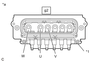
*1 Shield Ground *a Motor Cable (for MG2)
(Inverter with Converter Assembly Side)
Using a megohmmeter set to 500 V, measure the resistance according to the value(s) in the table below while rotating the front wheels 2 revolutions in the same direction simultaneously.
Note
-
Carefully perform this inspection as the motor (MG2) may generate current when the front wheels are rotated by hand.
-
Be sure to set the megohmmeter to 500 V when performing this test. Using a setting higher than 500 V can result in damage to the component being inspected.
Standard Resistance Tester Connection Condition Specified Condition g2-2 (U) - Body ground and shield ground Power switch on (IG) 100 MΩ or higher g2-3 (V) - Body ground and shield ground Power switch on (IG) 100 MΩ or higher g2-1 (W) - Body ground and shield ground Power switch on (IG) 100 MΩ or higher -
-
Lower the vehicle and push the P position switch (transmission shift main switch).
-
Turn the power switch off.
-
Disconnect the cable from the negative (-) auxiliary battery terminal.
Result Proceed to OK NG
NG
CHECK MOTOR CABLE (FOR MG2) Click here
OK
-
-
CHECK HYBRID VEHICLE TRANSAXLE ASSEMBLY (MOTOR CABLE (FOR MG1))
CAUTION:
Be sure to wear insulated gloves.
-
Check that the service plug grip is not installed.
Note
After removing the service plug grip, do not turn the power switch on (READY), unless instructed by the repair manual because this may cause a malfunction.
-
Connect the cable to the negative (-) auxiliary battery terminal.
Tech Tips
As the insulation resistance may vary when generator (MG1) rotates, perform this inspection while rotating the front wheels.
-
Turn the power switch on (IG).
Note
Turning the power switch on (IG) with the service plug grip removed causes DTCs to be stored. Clear the DTCs after performing this inspection.
-
Move the shift lever to N and lift the vehicle.
-
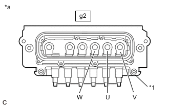
*1 Shield Ground *a Motor Cable (for MG1)
(Inverter with Converter Assembly Side)
Using a megohmmeter set to 500 V, measure the resistance according to the value(s) in the table below while rotating the front wheels 2 revolutions in the same direction simultaneously.
Note
-
Carefully perform this inspection as the generator (MG1) may generate current when the front wheels are rotated by hand.
-
Be sure to set the megohmmeter to 500 V when performing this test. Using a setting higher than 500 V can result in damage to the component being inspected.
Standard Resistance Tester Connection Condition Specified Condition g2-5 (U) - Body ground and shield ground Power switch on (IG) 100 MΩ or higher g2-6 (V) - Body ground and shield ground Power switch on (IG) 100 MΩ or higher g2-4 (W) - Body ground and shield ground Power switch on (IG) 100 MΩ or higher -
-
Lower the vehicle and push the P position switch (transmission shift main switch).
-
Turn the power switch off.
-
Disconnect the cable from the negative (-) auxiliary battery terminal.
Result Proceed to OK NG
NG
CHECK MOTOR CABLE (FOR MG1) Click here
OK
-
-
CHECK AIR CONDITIONING WIRE
CAUTION:
Be sure to wear insulated gloves.
-
Check that the service plug grip is not installed.
Note
After removing the service plug grip, do not turn the power switch on (READY), unless instructed by the repair manual because this may cause a malfunction.
-
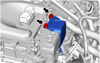
Disconnect the air conditioning wire connector from the inverter with converter assembly.
Tech Tips
Make sure that no foreign matter has entered or contaminated the air conditioning wire.
-
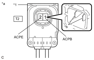
*1 Shield Ground *a Air conditioning wire
(Inverter with Converter Assembly Side)
*b Tip of Terminal Using a megohmmeter set to 500 V, measure the resistance according to the value(s) in the table below.
Note
-
Be sure to set the megohmmeter to 500 V when performing this test. Using a setting higher than 500 V can result in damage to the component being inspected.
-
Be sure to inspect with connecting the tester probes to the tips of the terminal.
Standard Resistance Tester Connection Condition Specified Condition T2-1 (ACPB) - Body ground and shield ground Power switch off 3 MΩ or higher T2-2 (ACPE) - Body ground and shield ground Power switch off 3 MΩ or higher Result Proceed to OK NG -
NG
GO TO STEP 49 Click here
OK
-
-
CHECK HV FLOOR UNDER WIRE
CAUTION:
Be sure to wear insulated gloves.
-
Check that the service plug grip is not installed.
Note
After removing the service plug grip, do not turn the power switch on (READY), unless instructed by the repair manual because this may cause a malfunction.
-
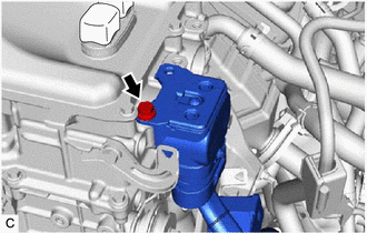
Disconnect the HV floor under wire connector from the inverter with converter assembly.
Tech Tips
Make sure that no foreign matter has entered or contaminated the HV floor under wire.
-
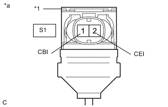
*1 Shield Ground *a HV Floor Under Wire
(Inverter with Converter Assembly Side)
Using a megohmmeter set to 500 V, measure the resistance according to the value(s) in the table below.
Note
-
Be sure to set the megohmmeter to 500 V when performing this test. Using a setting higher than 500 V can result in damage to the component being inspected.
-
Be sure not to damage or deform the terminal being inspected.
Standard Resistance Tester Connection Condition Specified Condition S1-1 (CBI) - Body ground and shield ground Power switch off 10 MΩ or higher S1-2 (CEI) - Body ground and shield ground Power switch off 10 MΩ or higher Tech Tips
Visually inspect the HV floor under wire for damage. If there is any damage, then this is the likely cause of low insulation resistance.
Result Proceed to OK NG -
NG
GO TO STEP 47 Click here
OK
-
-
CHECK INVERTER WITH CONVERTER ASSEMBLY
CAUTION:
Be sure to wear insulated gloves.
-
Check that the service plug grip is not installed.
Note
After removing the service plug grip, do not turn the power switch on (READY), unless instructed by the repair manual because this may cause a malfunction.
-
Connect the HV floor under wire connector to the inverter with converter assembly.
-
*a High Voltage Terminal Using a megohmmeter set to 500 V, measure the resistance according to the value(s) in the table below.
Note
Be sure to set the megohmmeter to 500 V when performing this test. Using a setting higher than 500 V can result in damage to the component being inspected.
Standard Resistance Tester Connection Condition Specified Condition High voltage terminal - Body ground Power switch off 1 MΩ or higher Tech Tips
Perform this inspection with the motor cable and air conditioning wire disconnected from the inverter with converter assembly.
Result Proceed to OK NG
NG
GO TO STEP 46 Click here
OK
-
-
CHECK NO. 2 HV BATTERY JUNCTION BLOCK ASSEMBLY
CAUTION:
Be sure to wear insulated gloves and protective goggles.
-
Check that the service plug grip is not installed.
Note
After removing the service plug grip, do not turn the power switch on (READY), unless instructed by the repair manual because this may cause a malfunction.
-
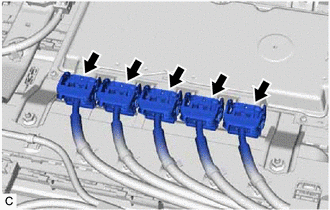
Remove the upper hybrid battery cover sub-assembly.
-
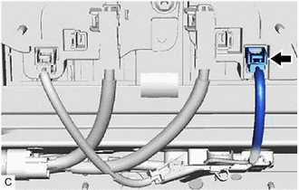
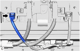
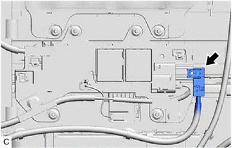
Disconnect the HV battery charger wire connector from the No. 2 HV battery junction block assembly.
-
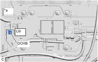
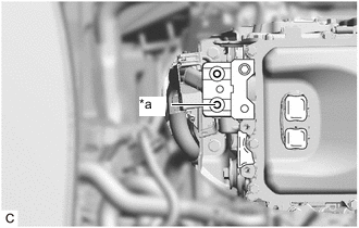
*a Component without harness connected
(No. 2 HV Battery Junction Block Assembly)
Using a megohmmeter set to 500 V, measure the resistance according to the value(s) in the table below.
Note
Be sure to set the megohmmeter to 500 V when performing this test. Using a setting higher than 500 V can result in damage to the component being inspected.
Standard Resistance Tester Connection Condition Specified Condition U9-1 (DCHB) - Body ground Power switch off 10 MΩ or higher Result Proceed to OK NG
NG
GO TO STEP 58 Click here
OK
-
-
CHECK NO. 1 HV BATTERY JUNCTION BLOCK ASSEMBLY
CAUTION:
Be sure to wear insulated gloves and protective goggles.
-
Check that the service plug grip is not installed.
Note
After removing the service plug grip, do not turn the power switch on (READY), unless instructed by the repair manual because this may cause a malfunction.
-
Disconnect the HV battery charger wire connector from the No. 1 HV battery junction block assembly.
-

*a Component without harness connected
(No. 1 HV Battery Junction Block Assembly)
Using a megohmmeter set to 500 V, measure the resistance according to the value(s) in the table below.
Note
Be sure to set the megohmmeter to 500 V when performing this test. Using a setting higher than 500 V can result in damage to the component being inspected.
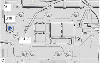
Standard Resistance Tester Connection Condition Specified Condition U10-1 (DCHG) - Body ground Power switch off 10 MΩ or higher Result Proceed to OK (w/ Solar Charging System) OK (w/o Solar Charging System) NG
OK (w/o Solar Charging System)
CHECK ELECTRIC VEHICLE CHARGER ASSEMBLY Click here
NG
GO TO STEP 66 Click here
OK (w/ Solar Charging System)
-
-
CHECK SOLAR ENERGY CONTROL UNIT
CAUTION:
Be sure to wear insulated gloves.
-
Check that the service plug grip is not installed.
Note
After removing the service plug grip, do not turn the power switch on (READY), unless instructed by the repair manual because this may cause a malfunction.
-
Remove the rear seat console box assembly.
-
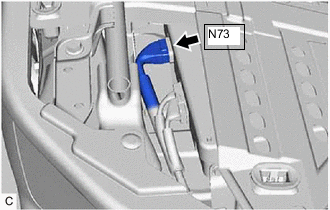
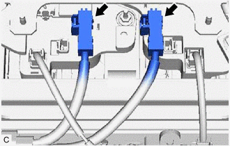
Disconnect the N73 solar energy control unit connector.
-
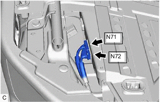
Disconnect the N71 and N72 solar energy control unit connectors.
-
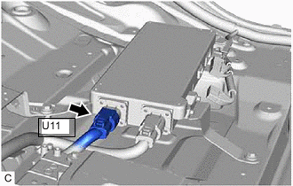
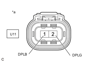
Disconnect the U11 solar energy control unit connector.
-
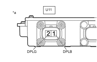
*a Component without harness connected
(Solar Energy Control Unit)
Using a megohmmeter set to 500 V, measure the resistance according to the value(s) in the table below.
Note
Be sure to set the megohmmeter to 500 V when performing this test. Using a setting higher than 500 V can result in damage to the component being inspected.
Standard Resistance Tester Connection Condition Specified Condition U11-1 (DPLB) - Body ground Power switch off 10 MΩ or higher U11-2 (DPLG) - Body ground Power switch off 10 MΩ or higher Result Proceed to OK NG
NG
GO TO STEP 59 Click here
OK
-
-
CHECK ELECTRIC VEHICLE CHARGER ASSEMBLY
CAUTION:
Be sure to wear insulated gloves.
-
Check that the service plug grip is not installed.
Note
After removing the service plug grip, do not turn the power switch on (READY), unless instructed by the repair manual because this may cause a malfunction.
-

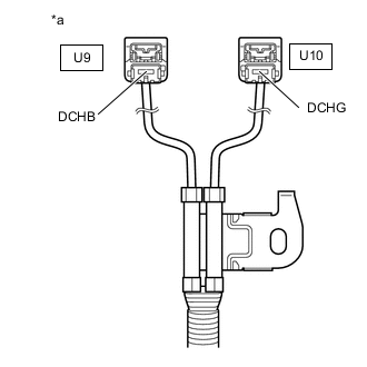
*a HV Battery Charger Wire
(Solar Energy Control Unit Side)
Using a megohmmeter set to 500 V, measure the resistance according to the value(s) in the table below.
Note
Be sure to set the megohmmeter to 500 V when performing this test. Using a setting higher than 500 V can result in damage to the component being inspected.
Standard Resistance Tester Connection Condition Specified Condition U11-1 (DPLB) - Body ground Power switch off 10 MΩ or higher U11-2 (DPLG) - Body ground Power switch off 10 MΩ or higher Result Proceed to OK NG
OK
GO TO STEP 19 Click here
NG
GO TO STEP 56 Click here
-
-
GO TO AIR CONDITIONING SYSTEM (P1C7C49)
Result Proceed to NEXT
NEXT
PERFORM CONFIRMATION AFTER REPLACING PARTS Click here
-
GO TO AIR CONDITIONING SYSTEM (P1C7C49)
Result Proceed to NEXT
NEXT
PERFORM CONFIRMATION AFTER REPLACING PARTS Click here
-
CHECK MOTOR CABLE (FOR MG2)
CAUTION:
Be sure to wear insulated gloves.
-
Check that the service plug grip is not installed.
Note
After removing the service plug grip, do not turn the power switch on (READY), unless instructed by the repair manual because this may cause a malfunction.
-
Remove the motor cable from the hybrid vehicle transaxle assembly.
-

*1 Shield Ground *a Motor Cable (for MG2)
(Inverter with Converter Assembly Side)
Using a megohmmeter set to 500 V, measure the resistance according to the value(s) in the table below.
Note
Be sure to set the megohmmeter to 500 V when performing this test. Using a setting higher than 500 V can result in damage to the component being inspected.
Standard Resistance Tester Connection Condition Specified Condition g2-2 (U) - Body ground and shield ground Power switch off 100 MΩ or higher g2-3 (V) - Body ground and shield ground Power switch off 100 MΩ or higher g2-1 (W) - Body ground and shield ground Power switch off 100 MΩ or higher Result Proceed to OK NG
OK
GO TO STEP 41 Click here
NG
GO TO STEP 42 Click here
-
-
CHECK MOTOR CABLE (FOR MG1)
CAUTION:
Be sure to wear insulated gloves.
-
Check that the service plug grip is not installed.
Note
After removing the service plug grip, do not turn the power switch on (READY), unless instructed by the repair manual because this may cause a malfunction.
-
Remove the motor cable from the hybrid vehicle transaxle assembly.
-

*1 Shield Ground *a Motor Cable (for MG1)
(Inverter with Converter Assembly Side)
Using a megohmmeter set to 500 V, measure the resistance according to the value(s) in the table below.
Note
Be sure to set the megohmmeter to 500 V when performing this test. Using a setting higher than 500 V can result in damage to the component being inspected.
Standard Resistance Tester Connection Condition Specified Condition g2-5 (U) - Body ground and shield ground Power switch off 100 MΩ or higher g2-6 (V) - Body ground and shield ground Power switch off 100 MΩ or higher g2-4 (W) - Body ground and shield ground Power switch off 100 MΩ or higher Result Proceed to OK NG
OK
GO TO STEP 41 Click here
NG
GO TO STEP 43 Click here
-
-
CHECK ELECTRIC VEHICLE CHARGER ASSEMBLY
CAUTION:
Be sure to wear insulated gloves and protective goggles.
-
Check that the service plug grip is not installed.
Note
After removing the service plug grip, do not turn the power switch on (READY), unless instructed by the repair manual because this may cause a malfunction.
-

*a HV Battery Charger Wire
(HV Battery Junction Block Assembly Side)
Using a megohmmeter set to 500 V, measure the resistance according to the value(s) in the table below.
Note
Be sure to set the megohmmeter to 500 V when performing this test. Using a setting higher than 500 V can result in damage to the component being inspected.
Standard Resistance Tester Connection Condition Specified Condition U9-1 (DCHB) - Body ground Power switch off 10 MΩ or higher U10-1 (DCHG) - Body ground Power switch off 10 MΩ or higher Result Proceed to OK NG
NG
GO TO STEP 63 Click here
OK
-
-
CHECK HV BATTERY (HIGH VOLTAGE CABLE)
CAUTION:
Be sure to wear insulated gloves and protective goggles.
Tech Tips
Make sure that no foreign matter or water has entered the HV battery.
-
Check that the service plug grip is not installed.
Note
After removing the service plug grip, do not turn the power switch on (READY), unless instructed by the repair manual because this may cause a malfunction.
-
Disconnect the battery ECU assembly connectors.
Note
Insulate each disconnected high-voltage connector with insulating tape. Wrap the connector from the wire harness side to the end of the connector.
-
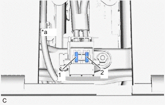
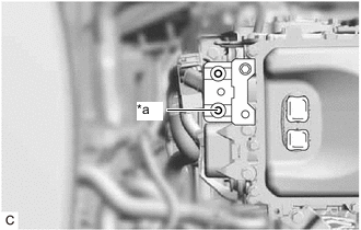
*a Service Plug Grip Removed
(Service Plug Grip Connecting Terminals)
Using a megohmmeter set to 500 V, measure the resistance according to the value(s) in the table below.
Note
Be sure to set the megohmmeter to 500 V when performing this test. Using a setting higher than 500 V can result in damage to the component being inspected.
Standard Resistance Tester Connection Condition Specified Condition 1 - Body ground Power switch off 10 MΩ or higher 2 - Body ground Power switch off 10 MΩ or higher Result Proceed to OK NG
NG
CHECK ELECTRIC VEHICLE BATTERY PLUG Click here
OK
-
-
REPLACE BATTERY ECU ASSEMBLY
Result Proceed to NEXT
NEXT
PERFORM CONFIRMATION AFTER REPLACING PARTS Click here
-
CHECK ELECTRIC VEHICLE BATTERY PLUG
CAUTION:
Be sure to wear insulated gloves and protective goggles.
-
Check that the service plug grip is not installed.
Note
After removing the service plug grip, do not turn the power switch on (READY), unless instructed by the repair manual because this may cause a malfunction.
-
Disconnect the electric vehicle battery plug connector.
-
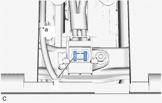
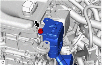
*a Service Plug Grip Removed
(Service Plug Grip Connecting Terminals)
Using a megohmmeter set to 500 V, measure the resistance according to the value(s) in the table below.
Note
Be sure to set the megohmmeter to 500 V when performing this test. Using a setting higher than 500 V can result in damage to the component being inspected.
Standard Resistance Tester Connection Condition Specified Condition 1 - Body ground Power switch off 10 MΩ or higher Result Proceed to OK NG
NG
REPLACE NO. 2 HV SUPPLY STACK SUB-ASSEMBLY Click here
OK
-
-
CHECK NO. 2 HV BATTERY JUNCTION BLOCK ASSEMBLY
CAUTION:
Be sure to wear insulated gloves and protective goggles.
-
Check that the service plug grip is not installed.
Note
After removing the service plug grip, do not turn the power switch on (READY), unless instructed by the repair manual because this may cause a malfunction.
-
Disconnect the high voltage cable connector of the HV battery from the No. 2 HV battery junction block assembly.
Note
Insulate each disconnected high-voltage connector with insulating tape. Wrap the connector from the wire harness side to the end of the connector.
-
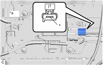
*a Component without harness connected
(No. 2 HV Battery Junction Block Assembly)
Using a megohmmeter set to 500 V, measure the resistance according to the value(s) in the table below.
Note
Be sure to set the megohmmeter to 500 V when performing this test. Using a setting higher than 500 V can result in damage to the component being inspected.
Standard Resistance Tester Connection Condition Specified Condition j1-1 (+) - Body ground Power switch off 10 MΩ or higher Result Proceed to OK NG
NG
GO TO STEP 58 Click here
OK
-
-
CHECK NO. 1 HV BATTERY JUNCTION BLOCK ASSEMBLY
CAUTION:
Be sure to wear insulated gloves and protective goggles.
-
Check that the service plug grip is not installed.
Note
After removing the service plug grip, do not turn the power switch on (READY), unless instructed by the repair manual because this may cause a malfunction.
-
Disconnect the high voltage cable connector of the HV battery from the No. 1 HV battery junction block assembly.
Note
Insulate each disconnected high-voltage connector with insulating tape. Wrap the connector from the wire harness side to the end of the connector.
-
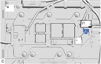
*a Component without harness connected
(No. 1 HV Battery Junction Block Assembly)
Using a megohmmeter set to 500 V, measure the resistance according to the value(s) in the table below.
Note
Be sure to set the megohmmeter to 500 V when performing this test. Using a setting higher than 500 V can result in damage to the component being inspected.
Standard Resistance Tester Connection Condition Specified Condition i1-1 (-) - Body ground Power switch off 10 MΩ or higher Result Proceed to OK NG
NG
GO TO STEP 66 Click here
OK
-
-
CHECK HV BATTERY
CAUTION:
Be sure to wear insulated gloves and protective goggles.
-
Check that no electrolyte is leaking from each HV supply stack sub-assembly.
Result Result Proceed to Electrolyte is not leaking from the HV supply stack sub-assembly. A Electrolyte is leaking from the HV supply stack sub-assembly. B
B
REPLACE HV BATTERY (HV supply stack sub-assembly that has a leak of electrolyte) Click here
A
-
-
CHECK NO. 5 HV SUPPLY STACK SUB-ASSEMBLY
CAUTION:
Be sure to wear insulated gloves and protective goggles.
-
Check that the service plug grip is not installed.
Note
After removing the service plug grip, do not turn the power switch on (READY), unless instructed by the repair manual because this may cause a malfunction.
-
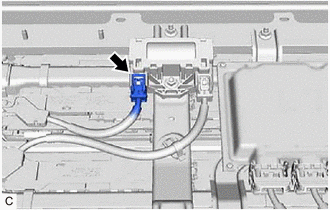
Disconnect the HV battery high voltage connector from the hybrid battery terminal block.
Note
Insulate each disconnected high-voltage connector with insulating tape. Wrap the connector from the wire harness side to the end of the connector.
-
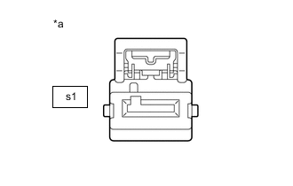
*a Component without harness connected
(Hybrid Battery Terminal Block Side)
Using a megohmmeter set to 500 V, measure the resistance according to the value(s) in the table below.
Note
Be sure to set the megohmmeter to 500 V when performing this test. Using a setting higher than 500 V can result in damage to the component being inspected.
Standard Resistance Tester Connection Condition Specified Condition s1-1 - Body ground Power switch off 10 MΩ or higher Result Proceed to OK NG
NG
REPLACE NO. 5 HV SUPPLY STACK SUB-ASSEMBLY Click here
OK
-
-
CHECK HYBRID BATTERY TERMINAL BLOCK
CAUTION:
Be sure to wear insulated gloves and protective goggles.
-
Check that the service plug grip is not installed.
Note
After removing the service plug grip, do not turn the power switch on (READY), unless instructed by the repair manual because this may cause a malfunction.
-
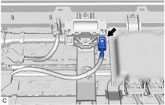
Disconnect the HV battery high voltage connector from the hybrid battery terminal block.
Note
Insulate each disconnected high-voltage connector with insulating tape. Wrap the connector from the wire harness side to the end of the connector.
-
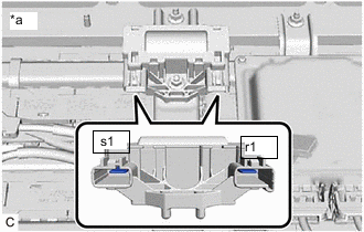
*a Component without harness connected
(Hybrid Battery Terminal Block)
Using a megohmmeter set to 500 V, measure the resistance according to the value(s) in the table below.
Note
Be sure to set the megohmmeter to 500 V when performing this test. Using a setting higher than 500 V can result in damage to the component being inspected.
Standard Resistance Tester Connection Condition Specified Condition s1-1 - Body ground Power switch off 10 MΩ or higher r1-1 - Body ground Power switch off 10 MΩ or higher Result Proceed to OK NG
NG
REPLACE HYBRID BATTERY TERMINAL BLOCK Click here
OK
-
-
CHECK NO. 4 HV SUPPLY STACK SUB-ASSEMBLY
CAUTION:
Be sure to wear insulated gloves and protective goggles.
-
Check that the service plug grip is not installed.
Note
After removing the service plug grip, do not turn the power switch on (READY), unless instructed by the repair manual because this may cause a malfunction.
-
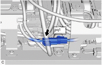
Disconnect the pq1 HV battery high voltage connector.
Note
Insulate each disconnected high-voltage connector with insulating tape. Wrap the connector from the wire harness side to the end of the connector.
-
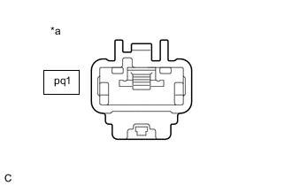
*a Component without harness connected
(No. 4 HV Supply Stack Sub-assembly Side)
Using a megohmmeter set to 500 V, measure the resistance according to the value(s) in the table below.
Note
Be sure to set the megohmmeter to 500 V when performing this test. Using a setting higher than 500 V can result in damage to the component being inspected.
Standard Resistance Tester Connection Condition Specified Condition pq1-1 - Body ground Power switch off 10 MΩ or higher Result Proceed to OK NG
NG
REPLACE NO. 4 HV SUPPLY STACK SUB-ASSEMBLY Click here
OK
-
-
CHECK NO. 3 HV SUPPLY STACK SUB-ASSEMBLY
CAUTION:
Be sure to wear insulated gloves and protective goggles.
-
Check that the service plug grip is not installed.
Note
After removing the service plug grip, do not turn the power switch on (READY), unless instructed by the repair manual because this may cause a malfunction.
-
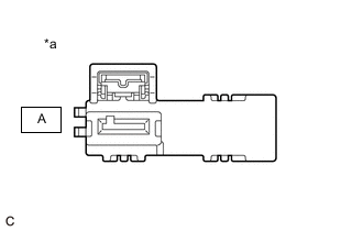
*a Component without harness connected
(No. 3 HV Supply Stack Sub-assembly Side)
Using a megohmmeter set to 500 V, measure the resistance according to the value(s) in the table below.
Note
Be sure to set the megohmmeter to 500 V when performing this test. Using a setting higher than 500 V can result in damage to the component being inspected.
Standard Resistance Tester Connection Condition Specified Condition A-1 - Body ground Power switch off 10 MΩ or higher Result Proceed to OK NG
NG
REPLACE NO. 3 HV SUPPLY STACK SUB-ASSEMBLY Click here
OK
-
-
CHECK NO. 2 HV SUPPLY STACK SUB-ASSEMBLY
CAUTION:
Be sure to wear insulated gloves and protective goggles.
-
Check that the service plug grip is not installed.
Note
After removing the service plug grip, do not turn the power switch on (READY), unless instructed by the repair manual because this may cause a malfunction.
-
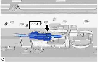
Disconnect the nm1 HV battery high voltage connector.
Note
Insulate each disconnected high-voltage connector with insulating tape. Wrap the connector from the wire harness side to the end of the connector.
-
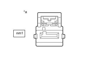
*a Component without harness connected
(No. 2 HV Supply Stack Sub-assembly Side)
Using a megohmmeter set to 500 V, measure the resistance according to the value(s) in the table below.
Note
Be sure to set the megohmmeter to 500 V when performing this test. Using a setting higher than 500 V can result in damage to the component being inspected.
Standard Resistance Tester Connection Condition Specified Condition nm1-1 - Body ground Power switch off 10 MΩ or higher Result Proceed to OK NG
NG
REPLACE NO. 2 HV SUPPLY STACK SUB-ASSEMBLY Click here
OK
-
-
REPLACE NO. 1 HV SUPPLY STACK SUB-ASSEMBLY
Result Proceed to NEXT
NEXT
PERFORM CONFIRMATION AFTER REPLACING PARTS Click here
-
REPLACE NO. 2 HV SUPPLY STACK SUB-ASSEMBLY
Result Proceed to NEXT
NEXT
PERFORM CONFIRMATION AFTER REPLACING PARTS Click here
-
REPLACE HV BATTERY (HV supply stack sub-assembly that has a leak of electrolyte)
Result Proceed to NEXT
NEXT
PERFORM CONFIRMATION AFTER REPLACING PARTS Click here
-
REPLACE NO. 5 HV SUPPLY STACK SUB-ASSEMBLY
Result Proceed to NEXT
NEXT
PERFORM CONFIRMATION AFTER REPLACING PARTS Click here
-
REPLACE HYBRID BATTERY TERMINAL BLOCK
Result Proceed to NEXT
NEXT
PERFORM CONFIRMATION AFTER REPLACING PARTS Click here
-
REPLACE NO. 4 HV SUPPLY STACK SUB-ASSEMBLY
Result Proceed to NEXT
NEXT
PERFORM CONFIRMATION AFTER REPLACING PARTS Click here
-
REPLACE NO. 3 HV SUPPLY STACK SUB-ASSEMBLY
Result Proceed to NEXT
NEXT
PERFORM CONFIRMATION AFTER REPLACING PARTS Click here
-
REPLACE NO. 2 HV SUPPLY STACK SUB-ASSEMBLY
Result Proceed to NEXT
NEXT
PERFORM CONFIRMATION AFTER REPLACING PARTS Click here
-
CHECK INVERTER WITH CONVERTER ASSEMBLY
CAUTION:
Be sure to wear insulated gloves.
-
Check that the service plug grip is not installed.
Note
After removing the service plug grip, do not turn the power switch on (READY), unless instructed by the repair manual because this may cause a malfunction.
-
Disconnect the motor cable from the inverter with converter assembly.
Tech Tips
Make sure that no foreign matter, coolant or water enters the inverter with converter assembly.
-
*a High Voltage Terminal Using a megohmmeter set to 500 V, measure the resistance according to the value(s) in the table below.
Note
Be sure to set the megohmmeter to 500 V when performing this test. Using a setting higher than 500 V can result in damage to the component being inspected.
Standard Resistance Tester Connection Condition Specified Condition High voltage terminal - Body ground Power switch off 1 MΩ or higher Tech Tips
Perform this inspection with the motor cable disconnected from the inverter with converter assembly.
Result Proceed to OK NG
NG
GO TO STEP 46 Click here
OK
-
-
CHECK MOTOR CABLE (FOR MG2)
CAUTION:
Be sure to wear insulated gloves.
-
Check that the service plug grip is not installed.
Note
After removing the service plug grip, do not turn the power switch on (READY), unless instructed by the repair manual because this may cause a malfunction.
-
Remove the motor cable from the hybrid vehicle transaxle assembly.
-

*1 Shield Ground *a Motor Cable (for MG2)
(Inverter with Converter Assembly Side)
Using a megohmmeter set to 500 V, measure the resistance according to the value(s) in the table below.
Note
Be sure to set the megohmmeter to 500 V when performing this test. Using a setting higher than 500 V can result in damage to the component being inspected.
Standard Resistance Tester Connection Condition Specified Condition g2-2 (U) - Body ground and shield ground Power switch off 100 MΩ or higher g2-3 (V) - Body ground and shield ground Power switch off 100 MΩ or higher g2-1 (W) - Body ground and shield ground Power switch off 100 MΩ or higher Result Proceed to OK NG
NG
REPLACE MOTOR CABLE Click here
OK
-
-
CHECK MOTOR CABLE (FOR MG1)
CAUTION:
Be sure to wear insulated gloves.
-
Check that the service plug grip is not installed.
Note
After removing the service plug grip, do not turn the power switch on (READY), unless instructed by the repair manual because this may cause a malfunction.
-
Remove the motor cable from the hybrid vehicle transaxle assembly.
-
*1 Shield Ground *a Motor Cable (for MG1)
(Inverter with Converter Assembly Side)
Using a megohmmeter set to 500 V, measure the resistance according to the value(s) in the table below.
Note
Be sure to set the megohmmeter to 500 V when performing this test. Using a setting higher than 500 V can result in damage to the component being inspected.
Standard Resistance Tester Connection Condition Specified Condition g2-5 (U) - Body ground and shield ground Power switch off 100 MΩ or higher g2-6 (V) - Body ground and shield ground Power switch off 100 MΩ or higher g2-4 (W) - Body ground and shield ground Power switch off 100 MΩ or higher Result Proceed to OK NG
NG
REPLACE MOTOR CABLE Click here
OK
-
-
REPLACE HYBRID VEHICLE TRANSAXLE ASSEMBLY
Result Proceed to NEXT
NEXT
PERFORM CONFIRMATION AFTER REPLACING PARTS Click here
-
REPLACE MOTOR CABLE
Result Proceed to NEXT
NEXT
PERFORM CONFIRMATION AFTER REPLACING PARTS Click here
-
REPLACE MOTOR CABLE
Result Proceed to NEXT
NEXT
PERFORM CONFIRMATION AFTER REPLACING PARTS Click here
-
CHECK HIGH VOLTAGE DIRECT CURRENT AREA
CAUTION:
Be sure to wear insulated gloves.
-
Check that the service plug grip is not installed.
Note
After removing the service plug grip, do not turn the power switch on (READY), unless instructed by the repair manual because this may cause a malfunction.
-
Disconnect the HV floor under wire connector from the inverter with converter assembly.
Tech Tips
Make sure that no foreign matter has entered or contaminated the HV floor under wire.
-
*1 Shield Ground *a HV Floor Under Wire
(Inverter with Converter Assembly Side)
Using a megohmmeter set to 500 V, measure the resistance according to the value(s) in the table below.
Note
-
Be sure to set the megohmmeter to 500 V when performing this test. Using a setting higher than 500 V can result in damage to the component being inspected.
-
Be sure not to damage or deform the terminal being inspected.
Standard Resistance Tester Connection Condition Specified Condition S1-1 (CBI) - Body ground and shield ground Power switch off 10 MΩ or higher S1-2 (CEI) - Body ground and shield ground Power switch off 10 MΩ or higher Tech Tips
Visually inspect the HV floor under wire for damage. If there is any damage, then this is the likely cause of low insulation resistance.
Result Proceed to OK NG -
NG
CHECK HV FLOOR UNDER WIRE Click here
OK
-
-
CHECK AIR CONDITIONING WIRE
CAUTION:
Be sure to wear insulated gloves.
-
Check that the service plug grip is not installed.
Note
After removing the service plug grip, do not turn the power switch on (READY), unless instructed by the repair manual because this may cause a malfunction.
-
Disconnect the air conditioning wire connector from the inverter with converter assembly.
Tech Tips
Make sure that no foreign matter has entered or contaminated the air conditioning wire.
-
*1 Shield Ground *a Air conditioning wire
(Inverter with Converter Assembly Side)
*b Tip of Terminal Using a megohmmeter set to 500 V, measure the resistance according to the value(s) in the table below.
Note
-
Be sure to set the megohmmeter to 500 V when performing this test. Using a setting higher than 500 V can result in damage to the component being inspected.
-
Be sure to inspect with connecting the tester probes to the tips of the terminal.
Standard Resistance Tester Connection Condition Specified Condition T2-1 (ACPB) - Body ground and shield ground Power switch off 3 MΩ or higher T2-2 (ACPE) - Body ground and shield ground Power switch off 3 MΩ or higher Result Proceed to OK NG -
NG
CHECK AIR CONDITIONING WIRE Click here
OK
-
-
REPLACE INVERTER WITH CONVERTER ASSEMBLY
Result Proceed to NEXT
NEXT
PERFORM CONFIRMATION AFTER REPLACING PARTS Click here
-
CHECK HV FLOOR UNDER WIRE
CAUTION:
Be sure to wear insulated gloves and protective goggles.
-
Check that the service plug grip is not installed.
Note
After removing the service plug grip, do not turn the power switch on (READY), unless instructed by the repair manual because this may cause a malfunction.
-
Remove the upper hybrid battery cover sub-assembly.
-
Disconnect the HV floor under wire connectors from the HV battery junction block assembly.
Tech Tips
Make sure that no foreign matter has entered or contaminated the HV floor under wire.
-
*1 Shield Ground *a HV Floor Under Wire
(Inverter with Converter Assembly Side)
Using a megohmmeter set to 500 V, measure the resistance according to the value(s) in the table below.
Note
-
Be sure to set the megohmmeter to 500 V when performing this test. Using a setting higher than 500 V can result in damage to the component being inspected.
-
Be sure not to damage or deform the terminal being inspected.
Standard Resistance Tester Connection Condition Specified Condition S1-1 (CBI) - Body ground Power switch off 10 MΩ or higher S1-2 (CEI) - Body ground Power switch off 10 MΩ or higher Tech Tips
Visually inspect the HV floor under wire for damage. If there is any damage, then this is the likely cause of low insulation resistance.
Result Proceed to OK NG -
NG
REPLACE HV FLOOR UNDER WIRE Click here
OK
-
-
CHECK NO. 2 HV BATTERY JUNCTION BLOCK ASSEMBLY
CAUTION:
Be sure to wear insulated gloves and protective goggles.
-
Check that the service plug grip is not installed.
Note
After removing the service plug grip, do not turn the power switch on (READY), unless instructed by the repair manual because this may cause a malfunction.
-
*a Component without harness connected
(No. 2 HV Battery Junction Block Assembly)
Using a megohmmeter set to 500 V, measure the resistance according to the value(s) in the table below.
Note
Be sure to set the megohmmeter to 500 V when performing this test. Using a setting higher than 500 V can result in damage to the component being inspected.
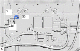
Standard Resistance Tester Connection Condition Specified Condition S3-1 (CBI) - Body ground Power switch off 10 MΩ or higher Result Proceed to OK NG
OK
GO TO STEP 66 Click here
NG
GO TO STEP 58 Click here
-
-
CHECK AIR CONDITIONING WIRE
CAUTION:
Be sure to wear insulated gloves.
-
Check that the service plug grip is not installed.
Note
After removing the service plug grip, do not turn the power switch on (READY), unless instructed by the repair manual because this may cause a malfunction.
-
Disconnect the air conditioning wire from the compressor with motor assembly.
-
*1 Shield Ground *a Air conditioning wire
(Inverter with Converter Assembly Side)
*b Tip of Terminal Using a megohmmeter set to 500 V, measure the resistance according to the value(s) in the table below.
Note
-
Be sure to set the megohmmeter to 500 V when performing this test. Using a setting higher than 500 V can result in damage to the component being inspected.
-
Be sure to inspect with connecting the tester probes to the tips of the terminal.
Standard Resistance Tester Connection Condition Specified Condition T2-1 (ACPB) - Body ground and shield ground Power switch off 10 MΩ or higher T2-2 (ACPE) - Body ground and shield ground Power switch off 10 MΩ or higher Result Proceed to OK NG -
NG
REPLACE AIR CONDITIONING WIRE Click here
OK
-
-
GO TO AIR CONDITIONING SYSTEM (P1C7C49)
Result Proceed to NEXT
NEXT
PERFORM CONFIRMATION AFTER REPLACING PARTS Click here
-
REPLACE AIR CONDITIONING WIRE
Result Proceed to NEXT
NEXT
PERFORM CONFIRMATION AFTER REPLACING PARTS Click here
-
REPLACE HV FLOOR UNDER WIRE
Result Proceed to NEXT
NEXT
PERFORM CONFIRMATION AFTER REPLACING PARTS Click here
-
CHECK NO. 2 HV BATTERY JUNCTION BLOCK ASSEMBLY
CAUTION:
Be sure to wear insulated gloves and protective goggles.
-
Check that the service plug grip is not installed.
Note
After removing the service plug grip, do not turn the power switch on (READY), unless instructed by the repair manual because this may cause a malfunction.
-
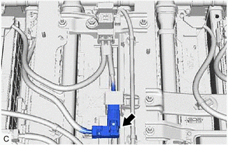
Remove the upper hybrid battery cover sub-assembly.
-
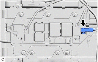
Disconnect the HV battery charger wire connector from the No. 2 HV battery junction block assembly.
-

*a Component without harness connected
(No. 2 HV Battery Junction Block Assembly)
Using a megohmmeter set to 500 V, measure the resistance according to the value(s) in the table below.
Note
Be sure to set the megohmmeter to 500 V when performing this test. Using a setting higher than 500 V can result in damage to the component being inspected.
Standard Resistance Tester Connection Condition Specified Condition U9-1 (DCHB) - Body ground Power switch off 10 MΩ or higher Result Proceed to OK NG
NG
REPLACE NO. 2 HV BATTERY JUNCTION BLOCK ASSEMBLY Click here
OK
-
-
CHECK NO. 1 HV BATTERY JUNCTION BLOCK ASSEMBLY
CAUTION:
Be sure to wear insulated gloves and protective goggles.
-
Check that the service plug grip is not installed.
Note
After removing the service plug grip, do not turn the power switch on (READY), unless instructed by the repair manual because this may cause a malfunction.
-
Disconnect the HV battery charger wire connector from the No. 1 HV battery junction block assembly.
-
*a Component without harness connected
(No. 1 HV Battery Junction Block Assembly)
Using a megohmmeter set to 500 V, measure the resistance according to the value(s) in the table below.
Note
Be sure to set the megohmmeter to 500 V when performing this test. Using a setting higher than 500 V can result in damage to the component being inspected.
Standard Resistance Tester Connection Condition Specified Condition U10-1 (DCHG) - Body ground Power switch off 10 MΩ or higher Result Proceed to OK (w/ Solar Charging System) OK (w/o Solar Charging System) NG
OK (w/o Solar Charging System)
CHECK HV BATTERY CHARGER WIRE Click here
NG
REPLACE NO. 1 HV BATTERY JUNCTION BLOCK ASSEMBLY Click here
OK (w/ Solar Charging System)
-
-
CHECK SOLAR ENERGY CONTROL UNIT
CAUTION:
Be sure to wear insulated gloves.
-
Check that the service plug grip is not installed.
Note
After removing the service plug grip, do not turn the power switch on (READY), unless instructed by the repair manual because this may cause a malfunction.
-
Remove the rear seat console box assembly.
-
Disconnect the N73 solar energy control unit connector.
-
Disconnect the N71 and N72 solar energy control unit connectors.
-
Disconnect the U11 solar energy control unit connector.
-
*a Component without harness connected
(Solar Energy Control Unit)
Using a megohmmeter set to 500 V, measure the resistance according to the value(s) in the table below.
Note
Be sure to set the megohmmeter to 500 V when performing this test. Using a setting higher than 500 V can result in damage to the component being inspected.
Standard Resistance Tester Connection Condition Specified Condition U11-1 (DPLB) - Body ground Power switch off 10 MΩ or higher U11-2 (DPLG) - Body ground Power switch off 10 MΩ or higher Result Proceed to OK NG
NG
CHECK HV BATTERY CHARGER WIRE Click here
OK
-
-
CHECK HV BATTERY CHARGER WIRE
CAUTION:
Be sure to wear insulated gloves.
-
Check that the service plug grip is not installed.
Note
After removing the service plug grip, do not turn the power switch on (READY), unless instructed by the repair manual because this may cause a malfunction.
-
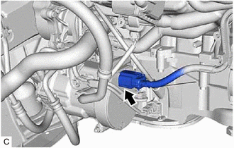
Disconnect the U12 electric vehicle charger assembly connector.
Tech Tips
Make sure that no foreign matter has entered or contaminated the HV floor under wire.
-
*a HV Battery Charger Wire
(Electric Vehicle Charger Assembly Side)
Using a megohmmeter set to 500 V, measure the resistance according to the value(s) in the table below.
Note
-
Be sure to set the megohmmeter to 500 V when performing this test. Using a setting higher than 500 V can result in damage to the component being inspected.
-
Be sure not to damage or deform the terminal being inspected.
Standard Resistance Tester Connection Condition Specified Condition U11-1 (DPLB) - Body ground Power switch off 10 MΩ or higher U11-2 (DPLG) - Body ground Power switch off 10 MΩ or higher Result Proceed to OK NG -
NG
REPLACE HV BATTERY CHARGER WIRE Click here
OK
-
-
REPLACE ELECTRIC VEHICLE CHARGER ASSEMBLY
Result Proceed to NEXT
NEXT
PERFORM CONFIRMATION AFTER REPLACING PARTS Click here
-
REPLACE NO. 2 HV BATTERY JUNCTION BLOCK ASSEMBLY
Result Proceed to NEXT
NEXT
PERFORM CONFIRMATION AFTER REPLACING PARTS Click here
-
CHECK HV BATTERY CHARGER WIRE
CAUTION:
Be sure to wear insulated gloves.
-
Check that the service plug grip is not installed.
Note
After removing the service plug grip, do not turn the power switch on (READY), unless instructed by the repair manual because this may cause a malfunction.
-
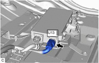
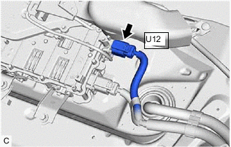
Disconnect the U13 solar energy control unit connector.
Tech Tips
Make sure that no foreign matter has entered or contaminated the HV floor under wire.
-
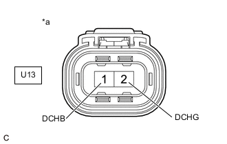
*a HV Battery Charger Wire
(Solar Energy Control Unit Side)
Using a megohmmeter set to 500 V, measure the resistance according to the value(s) in the table below.
Note
-
Be sure to set the megohmmeter to 500 V when performing this test. Using a setting higher than 500 V can result in damage to the component being inspected.
-
Be sure not to damage or deform the terminal being inspected.
Standard Resistance Tester Connection Condition Specified Condition U13-1 (DCHB) - Body ground Power switch off 10 MΩ or higher U13-2 (DCHG) - Body ground Power switch off 10 MΩ or higher Result Proceed to OK NG -
NG
REPLACE HV BATTERY CHARGER WIRE Click here
OK
-
-
REPLACE SOLAR ENERGY CONTROL UNIT
Result Proceed to NEXT
NEXT
PERFORM CONFIRMATION AFTER REPLACING PARTS Click here
-
REPLACE HV BATTERY CHARGER WIRE
Result Proceed to NEXT
NEXT
PERFORM CONFIRMATION AFTER REPLACING PARTS Click here
-
REPLACE HV BATTERY CHARGER WIRE
Result Proceed to NEXT
NEXT
PERFORM CONFIRMATION AFTER REPLACING PARTS Click here
-
CHECK HV BATTERY CHARGER WIRE
CAUTION:
Be sure to wear insulated gloves and protective goggles.
-
Check that the service plug grip is not installed.
Note
After removing the service plug grip, do not turn the power switch on (READY), unless instructed by the repair manual because this may cause a malfunction.
-
Disconnect the U12 electric vehicle charger assembly connector.
Tech Tips
Make sure that no foreign matter has entered or contaminated the HV floor under wire.
-
*a HV Battery Charger Wire
(HV Battery Junction Block Assembly Side)
Using a megohmmeter set to 500 V, measure the resistance according to the value(s) in the table below.
Note
-
Be sure to set the megohmmeter to 500 V when performing this test. Using a setting higher than 500 V can result in damage to the component being inspected.
-
Be sure not to damage or deform the terminal being inspected.
Standard Resistance Tester Connection Condition Specified Condition U9-1 (DCHB) - Body ground Power switch off 10 MΩ or higher U10-1 (DCHG) - Body ground Power switch off 10 MΩ or higher Result Proceed to OK NG -
NG
REPLACE HV BATTERY CHARGER WIRE Click here
OK
-
-
REPLACE ELECTRIC VEHICLE CHARGER ASSEMBLY
Result Proceed to NEXT
NEXT
PERFORM CONFIRMATION AFTER REPLACING PARTS Click here
-
REPLACE HV BATTERY CHARGER WIRE
Result Proceed to NEXT
NEXT
PERFORM CONFIRMATION AFTER REPLACING PARTS Click here
-
REPLACE NO. 1 HV BATTERY JUNCTION BLOCK ASSEMBLY
Result Proceed to NEXT
NEXT
PERFORM CONFIRMATION AFTER REPLACING PARTS Click here