HYBRID CONTROL SYSTEM, Diagnostic DTC:P31B300
| DTC Code | DTC Name |
|---|---|
| P31B300 | Hybrid/EV Battery Voltage High |
DTC SUMMARY
-
MALFUNCTION DESCRIPTION
The hybrid vehicle control ECU uses the inverter voltage, charge voltage and solar charge voltage to monitor the HV battery voltage and detect malfunctions.
The cause of this malfunction may be the following:
-
VL sensor malfunction
-
VH sensor malfunction
Inverter with converter assembly malfunction (Boost converter system)
-
Battery ECU assembly malfunction
-
HV battery malfunction
HV battery system
-
DESCRIPTION
The hybrid vehicle control ECU uses the inverter voltage, charge voltage and solar charge voltage to monitor the HV battery voltage and detect malfunctions.
| DTC No. | Detection Item | DTC Detection Condition | Trouble Area | MIL | Warning Indicate |
|---|---|---|---|---|---|
| P31B300 | Hybrid/EV Battery Voltage High | The inverter voltage exceeds the threshold. (1 trip detection logic) |
|
Comes on | Master Warning Light: Comes on |
*1: w/ Solar Charging System
CONFIRMATION DRIVING PATTERN
Tech Tips
After repair has been completed, clear the DTC and then check that the vehicle has returned to normal by performing the following All Readiness check procedure.
-
Connect the GTS to the DLC3.
-
Turn the power switch on (IG) and turn the GTS on.
-
Clear the DTCs (even if no DTCs are stored, perform the clear DTC procedure).
-
Turn the power switch off and wait for 2 minutes or more.
-
Turn the power switch on (IG) and turn the GTS on.
-
Turn the power switch on (READY) and wait for 30 seconds or more
-
Enter the following menus: Powertrain / Hybrid Control / Utility / All Readiness.
-
Check the DTC judgment result.
Tech Tips
-
If the judgment result shows NORMAL, the system is normal.
-
If the judgment result shows ABNORMAL, the system has a malfunction.
-
If the judgment result shows INCOMPLETE or N/A, perform driving pattern again.
-
CAUTION / NOTICE / HINT
CAUTION:
-

Before the following operations are conducted, take precautions to prevent electric shock by turning the power switch off, wearing insulated gloves, and removing the service plug grip from HV battery.
-
Inspecting the high-voltage system
-
Disconnecting the low voltage connector of the inverter with converter assembly
-
Disconnecting the low voltage connector of the HV battery
-
Disconnecting the low voltage connector of the electric vehicle charger assembly
-
Disconnecting the low voltage connector of the solar energy control unit
-

To prevent electric shock, make sure to remove the service plug grip to cut off the high voltage circuit before servicing the vehicle.
-

After removing the service plug grip from the HV battery, put it in your pocket to prevent other technicians from accidentally reconnecting it while you are working on the high-voltage system.
-
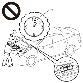
*a Without waiting for 10 minutes After removing the service plug grip, wait for at least 10 minutes before touching any of the high-voltage connectors or terminals. After waiting for 10 minutes, check the voltage at the terminals in the inspection point in the inverter with converter assembly. The voltage should be 0 V before beginning work.
Tech Tips
Waiting for at least 10 minutes is required to discharge the high-voltage capacitor inside the inverter with converter assembly.
-
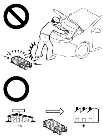
*a Dealer *b Battery Collection Agent Make sure to insulate the high-voltage connectors and terminals of the HV battery with insulating tape after removing it.
If the HV battery stored without insulating the connectors and terminals, electric shock or fire may result.
-
Accidents such as electric shock may result if the HV battery is disposed of improperly or abandoned. Therefore, make sure to return all HV batteries through an authorized collection agent.
-
When disposing of an HV battery, make sure to return it through an authorized collection agent who is capable of handling it safely. If the HV battery is returned via the manufacturer specified route, it will be returned properly and in a safe manner by an authorized collection agent.
-
Before returning the HV battery, make sure to perform a recovery inspection.
-
Before returning the HV supply stack sub-assembly, make sure to perform a recovery inspection.
-
Make a note of the output DTCs as some of them may be necessary for recovery inspection of the HV battery and HV supply stack sub-assemblies.
-
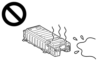
After removing the HV battery, keep it away from water. Exposure to water may cause the HV battery to produce heat, resulting in a fire.
Note
After turning the power switch off, waiting time may be required before disconnecting the cable from the negative (-) auxiliary battery terminal. Therefore, make sure to read the disconnecting the cable from the negative (-) auxiliary battery terminal notices before proceeding with work.
PROCEDURE
-
CHECK DTC OUTPUT (HYBRID CONTROL, MOTOR GENERATOR, , PLUG-IN CONTROL, SOLAR CHARGING CONTROL)
-
Connect the GTS to the DLC3.
-
Turn the power switch on (IG).
-
Enter the following menus: Powertrain / Hybrid Control, Motor Generator, Plug-in Control and Solar Charging Control / Trouble Codes.
-
Check for DTCs.
Powertrain > Hybrid Control > Trouble Codes
Powertrain > Motor Generator > Trouble Codes
Powertrain > Plug-in Control > Trouble Codes
Powertrain > Solar Charging Control > Trouble CodesResult Result Proceed to P31B300 only is output, or DTCs except the ones in the table below are also output. A DTCs of hybrid control system in the tables below are output. B DTCs of motor generator control system in the tables below are output. C DTCs of plug-in charge control system in the tables below are output. D DTCs of solar charging system in the tables below are output. E Malfunction Content System Relevant DTC Sensor and actuator circuit malfunction Hybrid control system P0D2D1C Drive Motor "A" Inverter Voltage Sensor Voltage Out of Range P0E311C Boosting Converter Voltage Sensor "A" Voltage Out of Range P0D4C1C Hybrid/EV Battery Charger Hybrid/EV Battery Input Voltage Sensor Voltage Out of Range P1C2D62 Hybrid/EV Battery "A" Voltage Sensor/Boosting Converter Voltage Sensor "A" Signal Compare Failure P1EA41C Hybrid/EV Control Battery Voltage Sensor / Solar Charging Voltage Sensor Voltage Out of Range P1EA917 Solar Charging Control Module Circuit Voltage Above Threshold P321D17 Charger Circuit Voltage Above Threshold Motor generator control system P0D2D16 Drive Motor "A" Inverter Voltage Sensor (VH) Circuit Voltage Below Threshold P0D2D17 Drive Motor "A" Inverter Voltage Sensor (VH) Circuit Voltage Above Threshold P0D2D1F Drive Motor "A" Inverter Voltage Sensor(VH) Circuit Intermittent P0E3116 DC/DC Converter Voltage Sensor "A" (VL) Circuit Voltage Below Threshold P0E3117 DC/DC Converter Voltage Sensor "A" (VL) Circuit Voltage Above Threshold P0E311F DC/DC Converter Voltage Sensor "A"(VL) Circuit Intermittent P0E5717 DC/DC Converter Voltage Sensor "A"(VL) Circuit Voltage Above Threshold Plug-in charge control system P0D4C12 Hybrid/EV Battery Charger Hybrid/EV Battery Input Voltage Sensor Circuit Short to Auxiliary Battery P0D4C14 Hybrid/EV Battery Charger Hybrid/EV Battery Input Voltage Sensor Circuit Short to Ground or Open Solar charging system P1EA412*1 Solar Charging Voltage Sensor Circuit Short to Auxiliary Battery P1EA414*1 Solar Charging Voltage Sensor Circuit Short to Ground or Open *1: w/ Solar Charging System
Tech Tips
-
P31B300 may be output as a result of the malfunction indicated by the DTCs above.
-
The chart above is listed in inspection order of priority.
-
Check DTCs that are output at the same time by following the listed order. (The main cause of the malfunction can be determined without performing unnecessary inspections.)
-
-
Turn the power switch off.
B 
GO TO DTC CHART (HYBRID CONTROL SYSTEM) Click here
C
GO TO DTC CHART (MOTOR GENERATOR CONTROL SYSTEM) Click here
D
GO TO DTC CHART (PLUG-IN CHARGE CONTROL SYSTEM) Click here
E
GO TO DTC CHART (SOLAR CHARGING SYSTEM) Click here
A 
-
-
READ VALUE USING GTS (HYBRID BATTERY VOLTAGE)
-
Connect the GTS to the DLC3.
-
Turn the power switch on (IG).
-
Enter the following menus: Powertrain / HV battery / Data List / Hybrid Battery Voltage
-
Read the Data List.
Powertrain > HV Battery > Data ListTester Display Hybrid Battery Voltage Note
Be sure not to measure when the power switch is on (READY).
-
Make a note of the data list item "Hybrid Battery Voltage".
-
Turn the power switch off.
Result Proceed to NEXT
NEXT
-
-
CHECK HV BATTERY
CAUTION:
Be sure to wear insulated gloves and protective goggles.
-
Check that the service plug grip is not installed.
Note
After removing the service plug grip, do not turn the power switch on (READY), unless instructed by the repair manual because this may cause a malfunction.
-
Remove the upper hybrid battery cover sub-assembly.
-
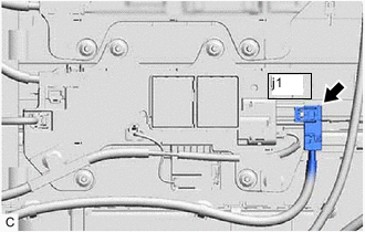
Disconnect the j1 HV battery high voltage connector from the No. 2 HV battery junction block assembly.
Note
Insulate each disconnected high-voltage connector with insulating tape. Wrap the connector from the wire harness side to the end of the connector.
-
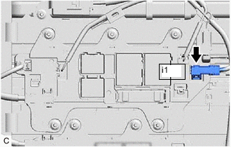
Disconnect the i1 HV battery high voltage connector from the No. 1 HV battery junction block assembly.
Note
Insulate each disconnected high-voltage connector with insulating tape. Wrap the connector from the wire harness side to the end of the connector.
-
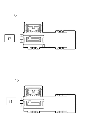
*a No. 5 HV Supply Stack Sub-assembly Connector
(No. 2 HV Battery Junction Block Assembly Side)
*b No. 1 HV Supply Stack Sub-assembly Connector
(No. 1 HV Battery Junction Block Assembly Side)
Measure the voltage according to the value(s) in the table below.
Standard Voltage Tester Connection Condition j1-1 - i1-1 Power switch off CAUTION:
Do not allow the probes of the electrical tester to contact each other during this inspection.
-
Check the value in the data list "Hybrid Battery Voltage" and the hybrid battery voltage value that was actually measured.
Result Result Proceed to When the difference between "Hybrid Battery Voltage" in the Data List and the measurement value of the HV battery voltage is 5 V or more. A Other than above (w/ Solar Charging System) B Other than above (w/o Solar Charging System) C -
Reconnect the i1 HV battery high voltage connector to the No. 1 HV battery junction block assembly.
-
Reconnect the j1 HV battery high voltage connector to the No. 2 HV battery junction block assembly.
-
Install the upper hybrid battery cover sub-assembly.
B 
CHECK FREEZE FRAME DATA (HYBRID CONTROL) Click here
C
CHECK FREEZE FRAME DATA (HYBRID CONTROL) Click here
A
-
-
REPLACE BATTERY ECU ASSEMBLY
Result Proceed to NEXT
NEXT
REPLACE HV SUPPLY STACK SUB-ASSEMBLY (NO. 1 THROUGH NO. 5) Click here
-
CHECK FREEZE FRAME DATA (HYBRID CONTROL)
-
Connect the GTS to the DLC3.
-
Turn the power switch on (IG).
-
Enter the following menus: Powertrain / Hybrid Control / Trouble Codes.
-
Read the freeze frame data of DTC P31B300.
Powertrain > Hybrid Control > Trouble CodesResult Result Proceed to Any of the following conditions is met.
-
"Charging Voltage for Hybrid Battery" is 437 V or more.
-
"Hybrid Battery Voltage" is less than 388 V.
A Any of the following conditions is met.
-
"Smoothed Value of Solar Charge Hybrid Battery DC/DC Converter Input Voltage" is 417 V or more.
-
"Hybrid Battery Voltage" is less than 388 V.
B Any of the following conditions is met.
-
"Charging Voltage for Hybrid Battery" is less than 437 V.
-
"Smoothed Value of Solar Charge Hybrid Battery DC/DC Converter Input Voltage" is less than 417 V.
-
"Hybrid Battery Voltage" is less than 388 V.
C Other than above D -
-
Turn the power switch off.
A
REPLACE ELECTRIC VEHICLE CHARGER ASSEMBLY Click here
B
REPLACE SOLAR ENERGY CONTROL UNIT Click here
C
REPLACE INVERTER WITH CONVERTER ASSEMBLY Click here
D
REPLACE BATTERY ECU ASSEMBLY Click here
-
-
CHECK FREEZE FRAME DATA (HYBRID CONTROL)
-
Connect the GTS to the DLC3.
-
Turn the power switch on (IG).
-
Enter the following menus: Powertrain / Hybrid Control / Trouble Codes.
-
Read the freeze frame data of DTC P31B300.
Powertrain > Hybrid Control > Trouble CodesResult Result Proceed to Any of the following conditions is met.
-
"Charging Voltage for Hybrid Battery" is 437 V or more.
-
"Hybrid Battery Voltage" is less than 388 V.
A Any of the following conditions is met.
-
"Charging Voltage for Hybrid Battery" is less than 437 V.
-
"Hybrid Battery Voltage" less than 388 V.
B Other than above C -
-
Turn the power switch off.
A
REPLACE ELECTRIC VEHICLE CHARGER ASSEMBLY Click here
B
REPLACE INVERTER WITH CONVERTER ASSEMBLY Click here
C
-
-
REPLACE BATTERY ECU ASSEMBLY
Result Proceed to NEXT
NEXT
REPLACE HV SUPPLY STACK SUB-ASSEMBLY (NO. 1 THROUGH NO. 5) Click here
-
REPLACE BATTERY ECU ASSEMBLY
Result Proceed to NEXT
NEXT
REPLACE HV SUPPLY STACK SUB-ASSEMBLY (NO. 1 THROUGH NO. 5) Click here