HYBRID CONTROL SYSTEM TERMINALS OF ECU
-
HYBRID VEHICLE CONTROL ECU
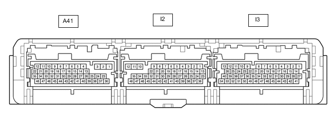
Terminal No.
(Symbol)
Wiring Color Input/Output Terminal Description Condition Specified Condition A41-4 (HMCH) - I3-3 (E1) B - W-B IN/OUT CAN Communication signal Power switch on (IG) Pulse generation
(Waveform 1)
A41-5 (MREL) - I3-3 (E1) W - W-B OUT IGCT SCENE relay Power switch on (IG) 11 to 14 V A41-6 (HSDN) - I3-3 (E1) B - W-B OUT MG ECU shutdown signal Power switch on (READY) 0 to 1.5 V A41-7 (STP) - I3-3 (E1) SB - W-B IN Stop light switch Brake pedal depressed 11 to 14 V Brake pedal released 0 to 1.5 V A41-8 (LIN3) - I3-3 (E1) G - W-B IN/OUT LIN communication signal
(A/C inverter, auxiliary battery)
Power switch on (READY) Pulse generation A41-11 (+B1) - I3-3 (E1) L - W-B IN Power source Power switch on (IG) 11 to 14 V A41-12 (OPM2) - I3-3 (E1) LG - W-B OUT OIL PMP relay Power switch on (READY), engine stopped 11 to 14 V A41-14 (HMCL) - I3-3 (E1) W - W-B IN/OUT Communication signal Power switch on (IG) Pulse generation
(Waveform 1)
A41-20 (BL) - I3-3 (E1) SB - W-B OUT Back-up light relay Power switch on (IG), shift lever in R 11 to 14 V A41-21 (OPM1) - I3-3 (E1) W - W-B OUT Oil pump with motor assembly signal Power switch on (READY), engine stopped Pulse generation
(Waveform 2)
A41-22 (NOPM) - I3-3 (E1) BR - W-B IN Oil pump with motor assembly signal Power switch on (READY), engine stopped Pulse generation
(Waveform 2)
A41-24 (VCPA) - A41-37 (EPA) BE - L OUT Accelerator pedal sensor assembly power source (for VPA) Power switch on (IG) 4.5 to 5.5 V A41-26 (VCP2) - A41-25 (EPA2) G - W OUT Accelerator pedal sensor assembly power source (for VPA2) Power switch on (IG) 4.5 to 5.5 V A41-33 (NIWP) - I3-3 (E1) GR - W-B IN Inverter water pump assembly signal Power switch on (READY) Pulse generation
(Waveform 3)
A41-34 (IWP) - I3-3 (E1) G - W-B OUT Inverter water pump assembly signal Power switch on (READY) Pulse generation
(Waveform 3)
A41-36 (VPA) - A41-37 (EPA) GR - L IN Accelerator pedal sensor assembly (for accelerator pedal position detection) Power switch on (IG), accelerator pedal released 0.4 to 1.4 V Power switch on (IG), engine stopped, shift position P, accelerator pedal fully depressed 2.6 to 4.5 V A41-38 (VPA2) - A41-25 (EPA2) B - W IN Accelerator pedal sensor assembly (for accelerator pedal sensor malfunction detection) Power switch on (IG), accelerator pedal released 1.0 to 2.2 V Power switch on (IG), engine stopped, shift position P, accelerator pedal fully depressed 3.4 to 5.3 V A41-40 (TTA) - A41-39 (ETTA) SB - P IN Transmission fluid temperature sensor Power switch on (IG), temperature 25°C (77°F) 3.6 to 4.6 V Power switch on (IG), temperature 60°C (140°F) 2.2 to 3.2 V A41-46 (MMT) - A41-45 (MMTG) L - BR IN Motor temperature sensor Power switch on (IG), temperature 25°C (77°F) 3.6 to 4.6 V Power switch on (IG), temperature 60°C (140°F) 2.2 to 3.2 V A41-48 (GMT) - A41-47 (GMTG) LG - R IN Generator temperature sensor Power switch on (IG), temperature 25°C (77°F) 3.6 to 4.6 V Power switch on (IG), temperature 60°C (140°F) 2.2 to 3.2 V I2-5 (ILK) - I3-3 (E1) V - W-B IN Interlock switch Power switch on (IG), service plug grip installed correctly 0 to 1.5 V Power switch on (IG), service plug grip not installed 11 to 14 V I2-7 (CA3P) - I3-3 (E1) G - W-B IN/OUT CAN communication signal Power switch on (IG) Pulse generation
(Waveform 4)
I2-8 (CA1L) - I3-3 (E1) W - W-B IN/OUT CAN communication signal Power switch on (IG) Pulse generation
(Waveform 5)
I2-9 (CA4H) - I3-3 (E1) SB - W-B IN/OUT CAN communication signal Power switch on (IG) Pulse generation
(Waveform 6)
I2-13 (SMRG) - I2-12 (E01) P - W-B OUT System main relay operation signal Power switch on (IG)→Power switch on (READY) Pulse generation
(Waveform 7)
I2-15 (SMRP) - I2-12 (E01) LG - W-B OUT System main relay operation signal Power switch on (IG)→Power switch on (READY) Pulse generation
(Waveform 7)
I2-16 (SMRB) - I2-12 (E01) BE - W-B OUT System main relay operation signal Power switch on (IG)→Power switch on (READY) Pulse generation
(Waveform 7)
I2-20 (CA3N) - I3-3 (E1) W - W-B IN/OUT CAN communication signal Power switch on (IG) Pulse generation
(Waveform 4)
I2-21 (CA1H) - I3-3 (E1) L - W-B IN/OUT CAN communication signal Power switch on (IG) Pulse generation
(Waveform 5)
I2-22 (CA4L) - I3-3 (E1) R - W-B IN/OUT CAN communication signal Power switch on (IG) Pulse generation
(Waveform 6)
I2-24 (CHEN) - I3-3 (E1) G - W-B OUT Charging permission signal Power switch on (IG) 0 to 1.5 V I2-31 (+B3M) - I3-3 (E1) L - W-B IN IGCT relay open monitor Power switch on (IG) 11 to 14 V I2-32 (MRL2) - I3-3 (E1) BE - W-B OUT IGCT relay Power switch on (IG) 11 to 14 V I2-35 (IG2) - I3-3 (E1) BE - W-B IN Power source Power switch on (IG) 11 to 14 V I3-1 (+B2) - I3-3 (E1) L - W-B IN Power source Power switch on (IG) 11 to 14 V I3-4 (ST2) - I3-3 (E1) B - W-B IN Starter signal Power switch on (IG) 0 to 1.5 V I3-18 (SSEN) - I3-3 (E1) L - W-B OUT Solar charging permission signal Solar charging permitted 2.0 to 14.5 V Solar charging prohibited Below 2 V I3-27 (BATT) - I3-3 (E1) GR - W-B IN Constant power source Always 10 to 14 V I3-29 (ABFS) - I3-3 (E1) B - W-B IN Airbag activation signal Power switch on (READY) Pulse generation
(Waveform 8)
I3-30 (TC) - I3-3 (E1) G - W-B IN Diagnosis terminal Power switch on (IG) 11 to 14 V I3-33 (EVHV) - I3-3 (E1) V - W-B IN HV/EV mode switch (pattern select switch assembly) signal Power switch on (IG), HV/EV mode switch (pattern select switch assembly) not operated 11 to 14 V Power switch on (IG), HV/EV mode switch (pattern select switch assembly) operated 0 to 1.5 V I3-34 (EVMS) - I3-3 (E1) GR - W-B IN EV city switch (pattern select switch assembly) signal*1 Power switch on (IG), EV city switch (pattern select switch assembly) not operated 11 to 14 V Power switch on (IG), EV city switch (pattern select switch assembly) operated 0 to 1.5 V EV auto switch (pattern select switch assembly) signal*2 Power switch on (IG), EV auto switch (pattern select switch assembly) not operated 11 to 14 V Power switch on (IG), EV auto switch (pattern select switch assembly) operated 0 to 1.5 V I3-37 (PDRV) - I3-3 (E1) G - W-B IN Drive mode select switch (pattern select switch assembly) signal Power switch on (IG), drive mode select switch (pattern select switch assembly) not operated 11 to 14 V Power switch on (IG), drive mode select switch (pattern select switch assembly) operated 0 to 1.5 V I3-44 (IGB) - I3-3 (E1) LG - W-B IN Power source Power switch on (IG) 11 to 14 V I3-46 (VSI4) - I3-49 (E2X2) W - BE IN Shift sensor (VSX4) Power switch on (IG), shift lever in home position 0.68 to 1.62 V Power switch on (IG), shift lever in D 4.47 to 4.75 V Power switch on (IG), shift lever in N 3.53 to 4.47 V Power switch on (IG), shift lever in R 2.75 to 3.52 V Power switch on (IG), shift lever in B 0.40 to 0.67 V I3-48 (VSI3) - I3-49 (E2X2) B - BE IN Shift sensor (VSX3) Power switch on (IG), shift lever in home position 1.63 to 2.70 V Power switch on (IG), shift lever in D 3.53 to 4.17 V Power switch on (IG), shift lever in N 2.45 to 3.52 V Power switch on (IG), shift lever in R 1.63 to 2.45 V Power switch on (IG), shift lever in B 0.98 to 2.45 V I3-50 (VSI2) - I3-51 (E2X1) R - GR IN Shift sensor (VSX2) Power switch on (IG), shift lever in home position 2.45 to 3.52 V Power switch on (IG), shift lever in D 2.70 to 3.52 V Power switch on (IG), shift lever in N 1.63 to 2.70 V Power switch on (IG), shift lever in R 0.98 to 1.62 V Power switch on (IG), shift lever in B 1.63 to 2.45 V I3-52 (VSI1) - I3-51 (E2X1) BR - GR IN Shift sensor (VSX1) Power switch on (IG), shift lever in home position 3.53 to 4.47 V Power switch on (IG), shift lever in D 1.63 to 2.40 V Power switch on (IG), shift lever in N 0.68 to 1.62 V Power switch on (IG), shift lever in R 0.40 to 0.67 V Power switch on (IG), shift lever in B 2.75 to 3.52 V I3-53 (VCX2) - I3-49 (E2X2) L - BE OUT Shift sensor power source (VCX2) Power switch on (IG) 4.5 to 5.5 V I3-54 (VCX1) - I3-51 (E2X1) V - GR OUT Shift sensor power source (VCX1) Power switch on (IG) 4.5 to 5.5 V *1: w/ EV CITY switch
*2: w/ EV AUTO switch
-
Oscilloscope waveforms
Tech Tips
Oscilloscope waveform samples are provided here for informational purposes. Noise and fluttering waveforms have been omitted.
-
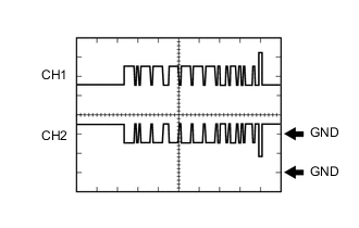
Waveform 1 (CAN communication signal)
Item Content Terminal CH1: A41-4 (HMCH) - I3-3 (E1)
CH2: A41-14 (HMCL) - I3-3 (E1)
Equipment Setting 1 V/DIV., 50 μs./DIV. Condition Power switch on (IG) Tech Tips
The waveform will vary depending on the content of the digital communication (digital signal).
-
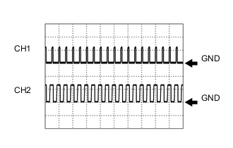
Waveform 2 (Oil pump with motor assembly signal)
Item Content Terminal CH1: A41-21 (OPM1) - I3-3 (E1)
CH2: A41-22 (NOPM) - I3-3 (E1)
Equipment Setting 10 V/DIV., 20 ms./DIV. Condition Power switch on (READY), engine stopped Tech Tips
The wavelength will vary with the operating speed of the oil pump.
-
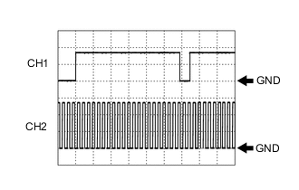
Waveform 3 (Inverter water pump assembly signal)
Item Content Terminal CH1: A41-34 (IWP) - I3-3 (E1)
CH2: A41-33 (NIWP) - I3-3 (E1)
Equipment Setting 5 V/DIV., 20 ms./DIV. Condition Power switch on (READY) -

Waveform 4 (CAN communication signal)
Item Content Terminal CH1: I2-7 (CA3P) - I3-3 (E1)
CH2: I2-20 (CA3N) - I3-3 (E1)
Equipment Setting 1 V/DIV., 50 μs./DIV. Condition Power switch on (IG) Tech Tips
The waveform will vary depending on the content of the digital communication (digital signal).
-
Waveform 5 (CAN communication signal)
Item Content Terminal CH1: I2-21 (CA1H) - I3-3 (E1)
CH2: I2-8 (CA1L) - I3-3 (E1)
Equipment Setting 1 V/DIV., 50 μs./DIV. Condition Power switch on (IG) Tech Tips
The waveform will vary depending on the content of the digital communication (digital signal).
-
Waveform 6 (CAN communication signal)
Item Content Terminal CH1: I2-9 (CA4H) - I3-3 (E1)
CH2: I2-22 (CA4L) - I3-3 (E1)
Equipment Setting 1 V/DIV., 50 μs./DIV. Condition Power switch on (IG) Tech Tips
The waveform will vary depending on the content of the digital communication (digital signal).
-
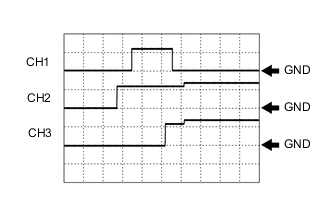
Waveform 7 (system main relay operation signal)
Item Content Terminal CH1: I2-15 (SMRP) - I2-12 (E01)
CH2: I2-16 (SMRB) - I2-12 (E01)
CH3: I2-13 (SMRG) - I2-12 (E01)
Equipment Setting 10 V/DIV., 200 ms./DIV. Condition Power switch on (IG) → Power switch on (READY) -
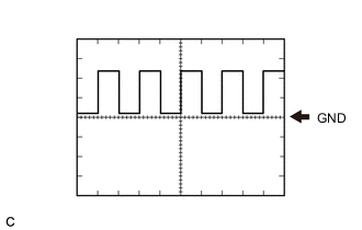
Waveform 8 (airbag activation signal)
Item Content Terminal I3-29 (ABFS) - I3-3 (E1) Equipment Setting 5 V/DIV., 125 ms./DIV. Condition Power switch on (READY)
-
-