HYBRID CONTROL SYSTEM, Diagnostic DTC:P082112, P082114, P082211, P082215, P181B62, P182112, P182114, P182211, P182215
| DTC Code | DTC Name |
|---|---|
| P082112 | Gear Lever X Position Sensor 1 Circuit Short to Auxiliary Battery |
| P082114 | Gear Lever X Position Sensor 1 Circuit Short to Ground or Open |
| P082211 | Gear Lever Y Position Sensor 1 Circuit Short to Ground |
| P082215 | Gear Lever Y Position Sensor 1 Circuit Short to Auxiliary Battery or Open |
| P181B62 | Gear Lever Position Sensor Signal Compare Failure |
| P182112 | Gear Lever X Position Sensor 2 Circuit Short to Auxiliary Battery |
| P182114 | Gear Lever X Position Sensor 2 Circuit Short to Ground or Open |
| P182211 | Gear Lever Y Position Sensor 2 Circuit Short to Ground |
| P182215 | Gear Lever Y Position Sensor 2 Circuit Short to Auxiliary Battery or Open |
DESCRIPTION
Tech Tips
-
The electronic shift lever system is a linkless type that does not use a shift cable.
-
The shift and select sensors are non-contact type sensors.
The shift lever (shift lock control unit assembly) is a momentary type, which returns to its home position by spring tension as the driver's hand is released from the shift lever after shifting.
The shift lever (shift lock control unit assembly) contains a shift sensor to detect the shift lever position (Home, R, N, D or B). Because the shift sensor operates using Hall ICs, they can accurately detect the shift lever position in a reliable manner.
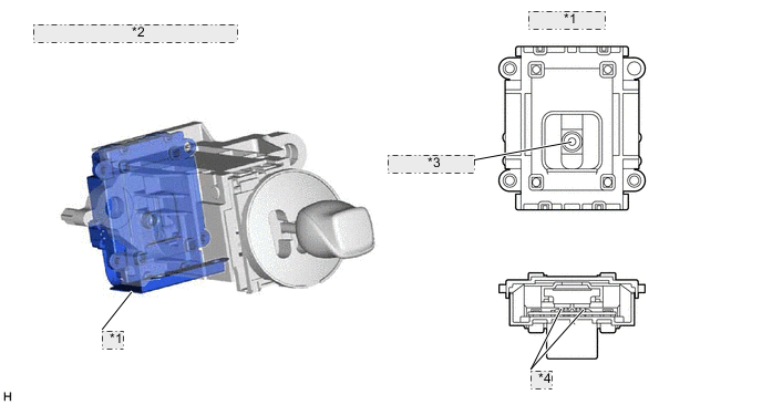
| *1 | Shift Sensor |
| *2 | Shift Lock Control Unit Assembly |
| *3 | Magnet Shift Position |
| *4 | Hall IC |
| DTC No. | Detection Item | DTC Detection Condition | Trouble Area | MIL | Warning Indicate |
|---|---|---|---|---|---|
| P082112 | Gear Lever X Position Sensor 1 Circuit Short to Auxiliary Battery | +B short in shift sensor 1 circuit (1 trip detection logic) |
|
Does not come on | Master Warning Light: Comes on |
| P082114 | Gear Lever X Position Sensor 1 Circuit Short to Ground or Open | Open or GND short in shift sensor 1 circuit (1 trip detection logic) |
|
Does not come on | Master Warning Light: Comes on |
| P082211 | Gear Lever Y Position Sensor 1 Circuit Short to Ground | Open or GND short in shift sensor 1 circuit (1 trip detection logic) |
|
Does not come on | Master Warning Light: Comes on |
| P082215 | Gear Lever Y Position Sensor 1 Circuit Short to Auxiliary Battery or Open | +B short in shift sensor 1 circuit (1 trip detection logic) |
|
Does not come on | Master Warning Light: Comes on |
| P181B62 | Gear Lever Position Sensor Signal Compare Failure | Shift sensor pattern malfunction (1 trip detection logic) |
|
Does not come on | Master Warning Light: Comes on |
| P182112 | Gear Lever X Position Sensor 2 Circuit Short to Auxiliary Battery | +B short in shift sensor 2 circuit (1 trip detection logic) |
|
Does not come on | Master Warning Light: Comes on |
| P182114 | Gear Lever X Position Sensor 2 Circuit Short to Ground or Open | Open or GND short in shift sensor 2 circuit (1 trip detection logic) |
|
Does not come on | Master Warning Light: Comes on |
| P182211 | Gear Lever Y Position Sensor 2 Circuit Short to Ground | Open or GND short in shift sensor 2 circuit (1 trip detection logic) |
|
Does not come on | Master Warning Light: Comes on |
| P182215 | Gear Lever Y Position Sensor 2 Circuit Short to Auxiliary Battery or Open | +B short in shift sensor 2 circuit (1 trip detection logic) |
|
Does not come on | Master Warning Light: Comes on |
CONFIRMATION DRIVING PATTERN
Tech Tips
After repair has been completed, clear the DTC and then check that the vehicle has returned to normal by performing the following All Readiness check procedure.
-
Connect the GTS to the DLC3.
-
Turn the power switch on (IG) and turn the GTS on.
-
Clear the DTCs (even if no DTCs are stored, perform the clear DTC procedure).
-
Turn the power switch off and wait for 2 minutes or more.
-
Turn the power switch on (IG) and turn the GTS on.
-
Turn the power switch on (READY).
-
With the brake pedal depressed, slowly move the shift lever as follows to select each shift state: N → R → N → D → N → Home → B → Home.
-
Push the P position switch (transmission shift main switch) to select park (P).
-
Enter the following menus: Powertrain / Hybrid Control / Utility / All Readiness.
-
Check the DTC judgment result.
Tech Tips
-
If the judgment result shows NORMAL, the system is normal.
-
If the judgment result shows ABNORMAL, the system has a malfunction.
-
If the judgment result shows INCOMPLETE or N/A, perform driving pattern again.
-
WIRING DIAGRAM
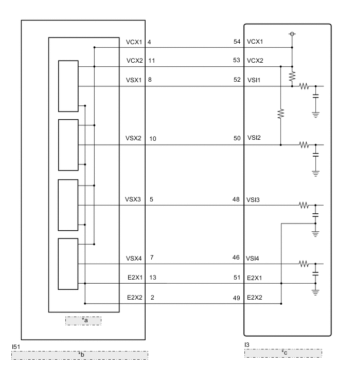
| *a | Shift Sensor |
| *b | Shift Lever (Shift Lock Control Unit Assembly) |
| *c | Hybrid Vehicle Control ECU |
PROCEDURE
-
READ VALUE USING GTS (SHIFT SENSOR VOLTAGE)
-
Connect the GTS the DLC3.
-
Turn the power switch on (READY).
-
Enter the following menus: Powertrain / Hybrid Control / Data List / Shift Sensor Voltage (VSI1), Shift Sensor Voltage (VSI2), Shift Sensor Voltage (VSI3), Shift Sensor Voltage (VSI4).
-
With the brake pedal depressed, while slowly move the shift lever as follows to select each shift state: N → R → N → D → N → Home → B → Home, read the Data List (Shift Sensor Voltage) displayed on the GTS.
Tech Tips
Wait with the shift lever in each state for 5 seconds or more.
Powertrain > Hybrid Control > Data ListTester Display Shift Sensor Voltage (VSI1) Shift Sensor Voltage (VSI2) Shift Sensor Voltage (VSI3) Shift Sensor Voltage (VSI4) Result Data List Item Shift Lever Position D N R B Home Shift Sensor Voltage (VSI1) 1.63 to 2.40 V 0.68 to 1.62 V 0.40 to 0.67 V 2.75 to 3.52 V 3.53 to 4.47 V Shift Sensor Voltage (VSI2) 2.70 to 3.52 V 1.63 to 2.70 V 0.98 to 1.62 V 1.63 to 2.45 V 2.45 to 3.52 V Shift Sensor Voltage (VSI3) 3.53 to 4.17 V 2.45 to 3.52 V 1.63 to 2.45 V 0.98 to 1.63 V 1.63 to 2.70 V Shift Sensor Voltage (VSI4) 4.47 to 4.75 V 3.53 to 4.47 V 2.75 to 3.52 V 0.40 to 0.67 V 0.68 to 1.62 V -
Push the P position switch (transmission shift main switch) to select park (P).
-
Turn the power switch off.
Result Proceed to OK NG
NG 
CHECK HARNESS AND CONNECTOR (HYBRID VEHICLE CONTROL ECU - SHIFT LOCK CONTROL UNIT ASSEMBLY) Click here
OK 
-
-
CHECK FOR INTERMITTENT PROBLEMS
Result Proceed to OK NG
OK 
REPLACE HYBRID VEHICLE CONTROL ECU Click here
NG
REPAIR OR REPLACE MALFUNCTIONING PARTS, COMPONENT AND AREA
-
CHECK HARNESS AND CONNECTOR (HYBRID VEHICLE CONTROL ECU - SHIFT LOCK CONTROL UNIT ASSEMBLY)
-
Disconnect the I3 hybrid vehicle control ECU connector.
-
Disconnect the I51 shift lock control unit assembly connector.
-
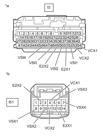
*a Front view of wire harness connector
(to Hybrid Vehicle Control ECU)
*b Front view of wire harness connector
(to Shift Lock Control Unit Assembly)
Measure the resistance according to the value(s) in the table below.
Standard Resistance (Check for Open) Tester Connection Condition Specified Condition I3-54 (VCX1) - I51-4 (VCX1) Power switch off Below 1 Ω I3-53 (VCX2) - I51-11 (VCX2) Power switch off Below 1 Ω I3-52 (VSI1) - I51-8 (VSX1) Power switch off Below 1 Ω I3-50 (VSI2) - I51-10 (VSX2) Power switch off Below 1 Ω I3-48 (VSI3) - I51-5 (VSX3) Power switch off Below 1 Ω I3-46 (VSI4) - I51-7 (VSX4) Power switch off Below 1 Ω I3-51 (E2X1) - I51-13 (E2X1) Power switch off Below 1 Ω I3-49 (E2X2) - I51-2 (E2X2) Power switch off Below 1 Ω Standard Resistance (Check for Short) Tester Connection Condition Specified Condition I3-54 (VCX1) or I51-4 (VCX1) - Body ground and terminals other than I51-11 (VCX2) Power switch off 10 kΩ or higher I3-53 (VCX2) or I51-11 (VCX2) - Body ground and terminals other than I51-4 (VCX1) Power switch off 10 kΩ or higher I3-52 (VSI1) or I51-8 (VSX1) - Body ground and other terminals Power switch off 10 kΩ or higher I3-50 (VSI2) or I51-10 (VSX2) - Body ground and other terminals Power switch off 10 kΩ or higher I3-48 (VSI3) or I51-5 (VSX3) - Body ground and other terminals Power switch off 10 kΩ or higher I3-46 (VSI4) or I51-7 (VSX4) - Body ground and other terminals Power switch off 10 kΩ or higher I3-51 (E2X1) or I51-13 (E2X1) - Body ground and terminals other than I51-2 (E2X2) Power switch off 10 kΩ or higher I3-49 (E2X2) or I51-2 (E2X2) - Body ground and terminals other than I51-13 (E2X1) Power switch off 10 kΩ or higher -
Connect the cable to the negative (-) auxiliary battery terminal.
-
Turn the power switch on (IG).
-
Measure the voltage according to the value(s) in the table below.
Standard Voltage Tester Connection Condition Specified Condition I3-54 (VCX1) or I51-4 (VCX1) - Body ground Power switch on (IG) Below 1 V I3-53 (VCX2) or I51-11 (VCX2) - Body ground Power switch on (IG) Below 1 V I3-52 (VSI1) or I51-8 (VSX1) - Body ground Power switch on (IG) Below 1 V I3-50 (VSI2) or I51-10 (VSX2) - Body ground Power switch on (IG) Below 1 V I3-48 (VSI3) or I51-5 (VSX3) - Body ground Power switch on (IG) Below 1 V I3-46 (VSI4) or I51-7 (VSX4) - Body ground Power switch on (IG) Below 1 V I3-51 (E2X1) or I51-13 (E2X1) - Body ground Power switch on (IG) Below 1 V I3-49 (E2X2) or I51-2 (E2X2) - Body ground Power switch on (IG) Below 1 V Note
Turning the power switch on (IG) with the hybrid vehicle control ECU and shift lock control unit assembly connectors disconnected causes other DTCs to be stored. Clear the DTCs after performing this inspection.
-
Turn the power switch off.
-
Disconnect the cable from the negative (-) auxiliary battery terminal.
-
Reconnect the I51 shift lock control unit assembly connector.
-
Reconnect the I3 hybrid vehicle control ECU connector.
Result Proceed to OK NG
NG
REPAIR OR REPLACE HARNESS OR CONNECTOR
OK
-
-
CHECK HYBRID VEHICLE CONTROL ECU (VCX1, VCX2 VOLTAGE)
-
Disconnect the I51 shift lock control unit assembly connector.
-
Turn the power switch on (IG).
-
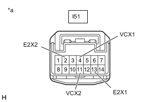
*a Front view of wire harness connector
(to Shift Lock Control Unit Assembly)
Measure the voltage according to the value(s) in the table below.
Standard Voltage Tester Connection Condition Specified Condition I51-4 (VCX1) - I51-13 (E2X1) Power switch on (IG) 4.5 to 5.5 V I51-11 (VCX2) - I51-2 (E2X2) Power switch on (IG) 4.5 to 5.5 V Note
Turning the power switch on (IG) with the connector disconnected causes other DTCs to be stored. Clear the DTCs after performing this inspection.
-
Turn the power switch off.
-
Reconnect the I51 shift lock control unit assembly connector.
Result Proceed to OK NG
NG
REPLACE HYBRID VEHICLE CONTROL ECU Click here
OK
-
-
REPLACE SHIFT LOCK CONTROL UNIT ASSEMBLY
Result Proceed to NEXT
NEXT
-
CLEAR DTC
Result Proceed to NEXT
-
Connect the GTS to the DLC3.
-
Turn the power switch on (IG).
-
Enter the following menus: Powertrain / Hybrid Control / Trouble Codes.
-
Read and record the DTCs and freeze frame data.
Powertrain > Hybrid Control > Trouble Codes -
Clear the DTCs and freeze frame data.
Powertrain > Hybrid Control > Clear DTCs -
Turn the power switch off.
Result Proceed to NEXT
NEXT
-
-
CHECK DTC OUTPUT (HYBRID CONTROL)
-
Connect the GTS to the DLC3.
-
Turn the power switch on (READY).
-
With the brake pedal depressed, slowly move the shift lever as follows to select each shift state: N → R → N → D → N → Home → B → Home.
-
Push the P position switch (transmission shift main switch) to select park (P).
-
Enter the following menus: Powertrain / Hybrid Control / Trouble Codes.
-
Check for DTCs.
Powertrain > Hybrid Control > Trouble CodesResult Result Proceed to No DTCs are output. A P082112, P082114, P082211, P082215, P181B62, P182112, P182114, P182211 or P182215 is output again. B -
Turn the power switch off.
A
COMPLETED
B
REPLACE HYBRID VEHICLE CONTROL ECU Click here
-