HYBRID CONTROL SYSTEM, Diagnostic DTC:P085011, P085015
| DTC Code | DTC Name |
|---|---|
| P085011 | Park/Neutral Switch Circuit Short to Ground |
| P085015 | Park/Neutral Switch Circuit Short to Auxiliary Battery or Open |
DESCRIPTION
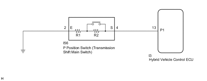
Instead of having a parking position as one of the positions as on a conventional shift lever, a P position switch (transmission shift main switch) is provided independently above the shift lever. The switch is a momentary type, in which the button does not lock mechanically.
The P position switch (transmission shift main switch) contains resistors R1 and R2. When the P position switch (transmission shift main switch) is not pressed, the switch provides a combined resistance of R1 and R2; and when the P position switch (transmission shift main switch) is pressed, the switch provides only the resistance of R1. The voltage at the P1 terminal of the hybrid vehicle control ECU varies with the changes in the resistance of the switch. The hybrid vehicle control ECU determines the P position switch (transmission shift main switch) operation according to this resistance signal.
| DTC No. | Detection Item | DTC Detection Condition | Trouble Area | MIL | Warning Indicate |
|---|---|---|---|---|---|
| P085011 | Park/Neutral Switch Circuit Short to Ground | GND short in P position switch circuit (1 trip detection logic) |
|
Does not come on | Master Warning Light: Comes on |
| P085015 | Park/Neutral Switch Circuit Short to Auxiliary Battery or Open | Open or +B short in P position switch circuit (1 trip detection logic) |
|
Does not come on | Master Warning Light: Comes on |
| DTC No. | Data List |
|---|---|
| P085011 |
|
| P085015 |
-
*1: While the P position switch (transmission shift main switch) is being pushed, the value for Data List item "P Position Switch Terminal Voltage" will decrease.
CONFIRMATION DRIVING PATTERN
Tech Tips
After repair has been completed, clear the DTC and then check that the vehicle has returned to normal by performing the following All Readiness check procedure.
-
Connect the GTS to the DLC3.
-
Turn the power switch on (IG) and turn the GTS on.
-
Clear the DTCs (even if no DTCs are stored, perform the clear DTC procedure).
-
Turn the power switch off and wait for 2 minutes or more.
-
Turn the power switch on (IG) and turn the GTS on.
-
Depress the brake pedal and move the shift lever to select neutral (N).
-
Push the P position switch (transmission shift main switch).
-
Enter the following menus: Powertrain / Hybrid Control / Utility / All Readiness.
-
Check the DTC judgment result.
Tech Tips
-
If the judgment result shows NORMAL, the system is normal.
-
If the judgment result shows ABNORMAL, the system has a malfunction.
-
If the judgment result shows INCOMPLETE or N/A, perform driving pattern again.
-
WIRING DIAGRAM
PROCEDURE
-
INSPECT P POSITION SWITCH (TRANSMISSION SHIFT MAIN SWITCH)
-
Disconnect the I56 P position switch (transmission shift main switch) connector.
-
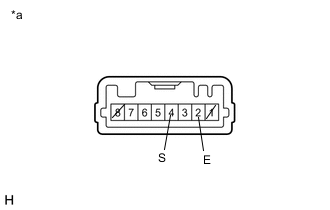
*a Component without harness connected
(P Position Switch (Transmission Shift Main Switch))
Measure the resistance according to the value(s) in the table below.
Standard Resistance Tester Connection Condition Specified Condition 4 (S) - 2 (E) Switch pressed 680 Ω 4 (S) - 2 (E) Switch released 4580 Ω Tech Tips
Terminals No. 1 and No. 8 on the component side connector are empty.
-
Reconnect the I56 P position switch (transmission shift main switch) connector.
Result Proceed to OK NG
NG 
REPLACE P POSITION SWITCH (TRANSMISSION SHIFT MAIN SWITCH)
OK 
-
-
CHECK HARNESS AND CONNECTOR (HYBRID VEHICLE CONTROL ECU - P POSITION SWITCH (TRANSMISSION SHIFT MAIN SWITCH))
-
Disconnect the I3 hybrid vehicle control ECU connector.
-
Disconnect the I56 P position switch (transmission shift main switch) connector.
-
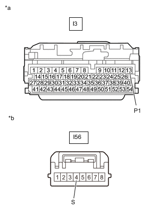
*a Front view of wire harness connector
(to Hybrid Vehicle Control ECU)
*b Front view of wire harness connector
(to P Position Switch (Transmission Shift Main Switch))
Measure the resistance according to the value(s) in the table below.
Standard Resistance (Check for Open) Tester Connection Condition Specified Condition I3-13 (P1) - I56-4 (S) Power switch off Below 1 Ω Standard Resistance (Check for Short) Tester Connection Condition Specified Condition I3-13 (P1) or I56-4 (S) - Body ground and other terminals Power switch off 10 kΩ or higher -
Connect the cable to the negative (-) auxiliary battery terminal.
-
Turn the power switch on (IG).
-
Measure the voltage according to the value(s) in the table below.
Standard Voltage Tester Connection Condition Specified Condition I3-13 (P1) or I56-4 (S) - Body ground Power switch on (IG) Below 1 V Note
Turning the power switch on (IG) with the hybrid vehicle control ECU and P position switch (transmission shift main switch) connectors disconnected causes other DTCs to be stored. Clear the DTCs after performing this inspection.
-
Turn the power switch off.
-
Disconnect the cable from the negative (-) auxiliary battery terminal.
-
Reconnect the I56 P position switch (transmission shift main switch) connector.
-
Reconnect the I3 hybrid vehicle control ECU connector.
Result Proceed to OK NG
NG
REPAIR OR REPLACE HARNESS OR CONNECTOR
OK
-
-
CHECK HARNESS AND CONNECTOR (P POSITION SWITCH (TRANSMISSION SHIFT MAIN SWITCH) - BODY GROUND)
-
Disconnect the I56 P position switch (transmission shift main switch) connector.
-
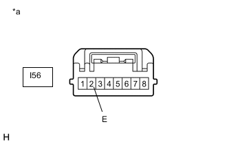
*a Front view of wire harness connector
(to P Position Switch (Transmission Shift Main Switch))
Measure the resistance according to the value(s) in the table below.
Standard Resistance (Check for Open) Tester Connection Condition Specified Condition I56-2 (E) - Body ground Power switch off Below 1 Ω -
Reconnect the I56 P position switch (transmission shift main switch) connector.
Result Proceed to OK NG
OK
REPLACE HYBRID VEHICLE CONTROL ECU Click here
NG
REPAIR OR REPLACE HARNESS OR CONNECTOR
-