SFI SYSTEM(w/o Canister Pump Module), Diagnostic DTC:P033562
| DTC Code | DTC Name |
|---|---|
| P033562 | Crankshaft Position Sensor "A" Signal Compare Failure |
DESCRIPTION
Refer to DTC P03352A.
| DTC No. | Detection Item | DTC Detection Condition | Trouble Area | MIL | Memory | Note |
|---|---|---|---|---|---|---|
| P033562 | Crankshaft Position Sensor "A" Signal Compare Failure | A camshaft position sensor signal is received but a crankshaft position sensor signal is not received after the engine is cranked (1 trip detection logic). |
|
Comes on | DTC stored | SAE Code: P0335 |
Reference: Inspection using an oscilloscope
MONITOR DESCRIPTION
When the engine is running, if the ECM does not receive a crankshaft position sensor signal while a camshaft position sensor signal is being received, the ECM will illuminate the MIL and store this DTC.
MONITOR STRATEGY
| Required Sensors/Components (Main) | Crankshaft position sensor |
| Required Sensors/Components (Related) | Camshaft position sensor |
| Frequency of Operation | Continuous |
CONFIRMATION DRIVING PATTERN
-
Connect the GTS to the DLC3.
-
Turn the power switch on (IG).
-
Turn the GTS on.
-
Clear the DTCs (even if no DTCs are stored, perform the clear DTC procedure).
-
Turn the power switch off and wait for at least 30 seconds.
-
Turn the power switch on (IG).
-
Turn the GTS on.
-
Put the engine in Inspection Mode (Maintenance Mode).
-
Start the engine.
-
Idle the engine for 20 seconds or more.
-
Enter the following menus: Powertrain / Engine / Trouble Codes.
-
Read the pending DTCs.
Tech Tips
-
If a pending DTC is output, the system is malfunctioning.
-
If a pending DTC is not output, perform the following procedure.
-
-
Enter the following menus: Powertrain / Engine / Utility / All Readiness.
-
Input the DTC: P033562.
-
Check the DTC judgment result.
GTS Display Description NORMAL
-
DTC judgment completed
-
System normal
ABNORMAL
-
DTC judgment completed
-
System abnormal
INCOMPLETE
-
DTC judgment not completed
-
Perform driving pattern after confirming DTC enabling conditions
N/A
-
Unable to perform DTC judgment
-
Number of DTCs which do not fulfill DTC preconditions has reached ECU memory limit
Tech Tips
-
If the judgment result is NORMAL, the system is normal.
-
If the judgment result is ABNORMAL, the system is malfunctioning.
-
If the judgment result is INCOMPLETE or N/A, perform the Confirmation Driving Pattern and check the DTC judgment result again.
-
CAUTION / NOTICE / HINT
Note
-
Vehicle Control History may be stored in the hybrid vehicle control ECU if the engine is malfunctioning. Certain vehicle condition information is recorded when Vehicle Control History is stored. Reading the vehicle conditions recorded in both the freeze frame data and Vehicle Control History can be useful for troubleshooting.
(Select Powertrain in Health Check and then check the time stamp data.)
-
If any "Engine Malfunction" Vehicle Control History item has been stored in the hybrid vehicle control ECU, make sure to clear it. However, as all Vehicle Control History items are cleared simultaneously, if any Vehicle Control History items other than "Engine Malfunction" are stored, make sure to perform any troubleshooting for them before clearing Vehicle Control History.
Tech Tips
-
After performing the inspection procedure for the crankshaft position sensor, if DTC P03352A, P033531 and/or P033562 is output again, check the following items related to the camshaft position sensor.
-
Installation condition of the camshaft position sensor.
-
Installation condition of the camshaft.
-
Connection of the camshaft position sensor connector.
-
If no problem is found through this diagnostic troubleshooting procedure, troubleshoot the engine mechanical system.
-
The engine speed can be checked by using the GTS. To perform the check, perform the following procedure:
-
Connect the GTS to the DLC3.
-
Turn the power switch on (IG).
-
Turn the GTS on.
-
Put the engine in Inspection Mode (Maintenance Mode).
-
Start the engine.
-
Enter the following menus: Powertrain / Engine / Data List / Engine Speed.
-
The engine speed may be indicated as zero despite the engine running normally. This is caused by a lack of NE signals from the crankshaft position sensor. Alternatively, the engine speed may be indicated as lower than the actual engine speed if the crankshaft position sensor output voltage is insufficient.
-
Read freeze frame data using the GTS. The ECM records vehicle and driving condition information as freeze frame data the moment a DTC is stored. When troubleshooting, freeze frame data can help determine if the vehicle was moving or stationary, if the engine was warmed up or not, if the air fuel ratio was lean or rich, and other data from the time the malfunction occurred.
PROCEDURE
-
CHECK SENSOR INSTALLATION (CRANKSHAFT POSITION SENSOR)
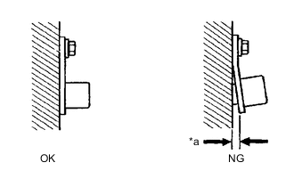
*a Clearance
-
Check the crankshaft position sensor installation condition.
OK Crankshaft position sensor is installed correctly. Result Proceed to OK NG
NG 
SECURELY REINSTALL CRANKSHAFT POSITION SENSOR Click here
OK 
-
-
CHECK SENSOR INSTALLATION (CAMSHAFT POSITION SENSOR)
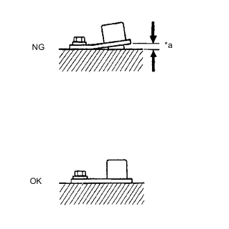
*a Clearance
-
Check the camshaft position sensor installation condition.
OK Camshaft position sensor is installed correctly. Result Proceed to OK NG
NG
SECURELY REINSTALL CAMSHAFT POSITION SENSOR Click here
OK
-
-
INSPECT NO. 1 CRANKSHAFT POSITION SENSOR PLATE (TEETH OF SENSOR PLATE)
-
Inspect the teeth of the No. 1 crankshaft position sensor plate.
OK No. 1 crankshaft position sensor plate does not have any cracks or deformation. Result Proceed to OK NG
NG
REPLACE NO. 1 CRANKSHAFT POSITION SENSOR PLATE Click here
OK
-
-
INSPECT INTAKE CAMSHAFT (TIMING ROTOR)
-
Check the timing rotor of the intake camshaft.
OK Camshaft timing rotor does not have any cracks or deformation. Result Proceed to OK NG
NG
REPLACE INTAKE CAMSHAFT Click here
OK
-
-
CHECK VALVE TIMING (CHECK FOR LOOSE TIMING CHAIN AND JUMPED TEETH)
-
Remove the cylinder head cover sub-assembly.
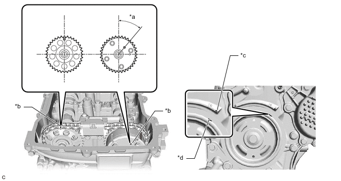
*a 39.5° *b Timing Mark *c "0" Timing Mark *d Groove -
Turn the crankshaft pulley and align its groove with the "0" timing mark of the timing chain or belt cover sub-assembly.
-
Check that the timing marks of the camshaft timing gear assembly and camshaft timing sprocket are at the positions shown in the illustration.
Tech Tips
If the timing marks are not as shown, turn the crankshaft one revolution clockwise.
OK Timing marks on camshaft timing gear assembly and camshaft timing sprocket are at the positions shown in the illustration. Tech Tips
If the result is not as specified, check for mechanical malfunctions that may have affected the valve timing, such as a jumped tooth or stretching of the timing chain.
Result Proceed to OK NG
OK 
GO TO STEP 7 Click here
NG
-
-
CHECK ENGINE MECHANICAL SYSTEM
-
Check for mechanical malfunctions that affect the valve timing, such as a jumped tooth or stretching of the timing chain.
Tech Tips
Perform "Inspection After Repair" after repairing or replacing the engine mechanical system.
Result Proceed to OK NG
NG
REPAIR OR REPLACE MALFUNCTIONING PARTS, COMPONENT AND AREA
OK
-
-
CLEAR DTC
-
Connect the GTS to the DLC3.
-
Turn the power switch on (IG).
-
Turn the GTS on.
-
Clear the DTCs.
Powertrain > Engine > Clear DTCs -
Turn the power switch off and wait for at least 30 seconds.
Result Proceed to NEXT
NEXT
-
-
CHECK WHETHER DTC OUTPUT RECURS (DTC P033562)
-
Drive the vehicle in accordance with the driving pattern described in Confirmation Driving Pattern.
-
Enter the following menus: Powertrain / Engine / Trouble Codes.
-
Read the DTCs.
Powertrain > Engine > Trouble CodesResult Result Proceed to DTCs are not output A DTC P033562 is output B
A
CHECK FOR INTERMITTENT PROBLEMS Click here
B
REPLACE ECM Click here
-