COOLING FAN SYSTEM Cooling Fan Circuit
DESCRIPTION
The cooling fans are controlled by the ECM and air conditioning amplifier assembly.
The ECM calculates an appropriate cooling fan speed based on the engine coolant temperature, air conditioning switch status, refrigerant pressure, engine speed and vehicle speed, and sends a signal to the cooling fan ECUs (cooling fan motors). The cooling fan ECUs (cooling fan motors) steplessly control the speed of the cooling fans based on the duty cycle signal sent from the ECM. By sending signals to the cooling fan ECUs (cooling fan motors) in accordance with the driving conditions and by controlling the cooling fan speed optimally with the ECM, both high cooling performance and quietness are ensured.
The air conditioning amplifier assembly sends a signal indicating the status of the remote air conditioning to the cooling fan ECUs (cooling fan motors). The cooling fan ECUs (cooling fan motors) control whether the cooling fans are on/off based on the signal sent from the air conditioning amplifier assembly.
CAUTION / NOTICE / HINT
Note
-
Inspect the fuses for circuits related to this system before performing the following procedure.
-
Perform Registration (VIN registration or frame number registration) after replacing the ECM.
w/ Canister Pump Module: Click here
w/o Canister Pump Module: Click here
PROCEDURE
-
CHECK DTC OUTPUT
-
Connect the GTS to the DLC3.
-
Turn the power switch on (IG).
-
Turn the GTS on.
-
Enter the following menus: System Select / Health Check.
-
Check for DTCs.
Result Result Proceed to DTCs are not output A DTC B1383 is output B DTC B227A is output C
B 
GO TO AIR CONDITIONING SYSTEM Click here
C
GO TO ENTRY AND START SYSTEM Click here
A 
-
-
CHECK COOLING FAN SYSTEM
-
Disconnect the A31 ECM connector.
-
Disconnect the I60 air conditioning amplifier assembly connector.
-
Turn the power switch on (IG).
-
Check the operation of the cooling fans.
OK The cooling fans operate. Result Result Proceed to OK A NG (fan RH does not operate) B NG (fan LH does not operate) C
B 
CHECK HARNESS AND CONNECTOR (COOLING FAN MOTOR RH - BODY GROUND) Click here
C
CHECK HARNESS AND CONNECTOR (COOLING FAN MOTOR LH - BODY GROUND) Click here
A
-
-
PERFORM ACTIVE TEST USING GTS (CONTROL THE ENGINE COOLING FAN DUTY RATIO)
-
Connect the GTS to the DLC3.
-
Turn the power switch on (IG).
-
Turn the GTS on.
-
Enter the following menus: Powertrain / Engine / Active Test / Control the Engine Cooling Fan Duty Ratio.
Powertrain > Engine > Active TestTester Display Control the Engine Cooling Fan Duty Ratio -
Check the operation of the cooling fans while operating them using the GTS.
OK Tester Operation Fan Operation 30 - 100% Cooling fans operate 0% Cooling fans stop Result Result Proceed to OK A NG (fans do not operate) B NG (fan RH does not stop) C NG (fan LH does not stop) D
A
REPLACE AIR CONDITIONING AMPLIFIER ASSEMBLY Click here
B
REPLACE ECM Click here
D
CHECK HARNESS AND CONNECTOR (COOLING FAN MOTOR LH - ECM AND AIR CONDITIONING AMPLIFIER ASSEMBLY) Click here
C
-
-
CHECK HARNESS AND CONNECTOR (COOLING FAN MOTOR RH - ECM AND AIR CONDITIONING AMPLIFIER ASSEMBLY)
-
Disconnect the A5 cooling fan motor RH connector.
-
Disconnect the A31 ECM connector.
-
Disconnect the I60 air conditioning amplifier assembly connector.
-
Measure the resistance according to the value(s) in the table below.
Standard Resistance Tester Connection Condition Specified Condition A5-3 (SI) - A31-60 (RFC) Always Below 1 Ω A5-3 (SI) - I60-12 (CFAN) Always Below 1 Ω Result Proceed to OK NG
OK
REPLACE COOLING FAN MOTOR RH
NG
REPAIR OR REPLACE HARNESS OR CONNECTOR
-
-
CHECK HARNESS AND CONNECTOR (COOLING FAN MOTOR LH - ECM AND AIR CONDITIONING AMPLIFIER ASSEMBLY)
-
Disconnect the A6 cooling fan motor LH connector.
-
Disconnect the A31 ECM connector.
-
Disconnect the I60 air conditioning amplifier assembly connector.
-
Measure the resistance according to the value(s) in the table below.
Standard Resistance Tester Connection Condition Specified Condition A6-3 (SI2) - A31-60 (RFC) Always Below 1 Ω A6-3 (SI2) - I60-12 (CFAN) Always Below 1 Ω Result Proceed to OK NG
OK
REPLACE COOLING FAN MOTOR LH
NG
REPAIR OR REPLACE HARNESS OR CONNECTOR
-
-
CHECK HARNESS AND CONNECTOR (COOLING FAN MOTOR RH - BODY GROUND)
-
Disconnect the A5 cooling fan motor RH connector.
-
Measure the resistance according to the value(s) in the table below.
Standard Resistance Tester Connection Condition Specified Condition A5-2 (E1) - Body ground Always Below 1 Ω Result Proceed to OK NG
NG
REPAIR OR REPLACE HARNESS OR CONNECTOR
OK
-
-
CHECK HARNESS AND CONNECTOR (COOLING FAN MOTOR RH POWER SOURCE)
-
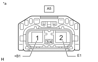
*a Front view of wire harness connector
(to Cooling Fan Motor RH)
Disconnect the A5 cooling fan motor RH connector.
-
Measure the voltage according to the value(s) in the table below.
Standard Voltage Tester Connection Condition Specified Condition A5-1 (+B1) - A5-2 (E1) Always 11 to 14 V Result Proceed to OK NG
OK
GO TO STEP 10 Click here
NG
REPAIR OR REPLACE HARNESS OR CONNECTOR (COOLING FAN MOTOR RH - AUXILIARY BATTERY)
-
-
CHECK HARNESS AND CONNECTOR (COOLING FAN MOTOR LH - BODY GROUND)
-
Disconnect the A6 cooling fan motor LH connector.
-
Measure the resistance according to the value(s) in the table below.
Standard Resistance Tester Connection Condition Specified Condition A6-2 (E2) - Body ground Always Below 1 Ω Result Proceed to OK NG
NG
REPAIR OR REPLACE HARNESS OR CONNECTOR
OK
-
-
CHECK HARNESS AND CONNECTOR (COOLING FAN MOTOR LH POWER SOURCE)
-
Disconnect the A6 cooling fan motor LH connector.
-
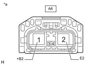
*a Front view of wire harness connector
(to Cooling Fan Motor LH)
Measure the voltage according to the value(s) in the table below.
Standard Voltage Tester Connection Condition Specified Condition A6-1 (+B2) - A6-2 (E2) Always 11 to 14 V Result Proceed to OK NG
NG
REPAIR OR REPLACE HARNESS OR CONNECTOR (COOLING FAN MOTOR LH - AUXILIARY BATTERY)
OK
-
-
CHECK HARNESS AND CONNECTOR (COOLING FAN MOTOR RH AND COOLING FAN MOTOR LH POWER SOURCE)
-
Disconnect the A5 cooling fan motor RH connector.
-
Disconnect the A6 cooling fan motor LH connector.
-
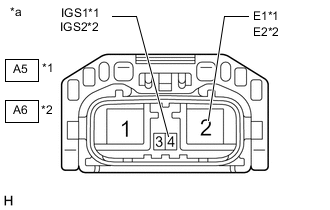
*1 Cooling Fan Motor RH *2 Cooling Fan Motor LH *a Front view of wire harness connector
(to Cooling Fan Motor RH and Cooling Fan Motor LH)
Measure the voltage according to the value(s) in the table below.
Standard Voltage Tester Connection Condition Specified Condition A5-4 (IGS1) - A5-2 (E1) Power switch on (IG) 11 to 14 V Remote climate control system on 11 to 14 V A6-4 (IGS2) - A6-2 (E2) Power switch on (IG) 11 to 14 V Remote climate control system on 11 to 14 V Result Result Proceed to OK A NG (Power switch on) B NG (Remote climate control system on) C NG (Power switch on and remote climate control system on) D
B
INSPECT FAN NO. 1 RELAY Click here
C
INSPECT FAN NO. 1 RELAY Click here
D
INSPECT FAN NO. 1 RELAY Click here
A
-
-
CHECK HARNESS AND CONNECTOR (COOLING FAN MOTOR RH AND COOLING FAN MOTOR LH - ECM AND AIR CONDITIONING AMPLIFIER ASSEMBLY)
-
Disconnect the A5 cooling fan motor RH connector.
-
Disconnect the A6 cooling fan motor LH connector.
-
Disconnect the A31 ECM connector.
-
Disconnect the I60 air conditioning amplifier assembly connector.
-
Measure the resistance according to the value(s) in the table below.
Standard Resistance Tester Connection Condition Specified Condition A5-3 (SI), A6-3 (SI2), A31-60 (RFC) or I60-12 (CFAN) - Body ground Always 10 kΩ or higher Result Proceed to OK NG
OK
PROCEED TO NEXT SUSPECTED AREA SHOWN IN PROBLEM SYMPTOMS TABLE Click here
NG
REPAIR OR REPLACE HARNESS OR CONNECTOR
-
-
INSPECT FAN NO. 1 RELAY
-
Inspect the FAN NO. 1 relay.
Result Proceed to OK NG
OK
REPAIR OR REPLACE HARNESS OR CONNECTOR (EFI-MAIN RELAY - FAN NO. 1 RELAY)
NG
REPLACE FAN NO. 1 RELAY
-
-
INSPECT FAN NO. 1 RELAY
-
Inspect the FAN NO. 1 relay.
Result Proceed to OK NG
NG
REPLACE FAN NO. 1 RELAY
OK
-
-
CHECK HARNESS AND CONNECTOR (FAN NO. 1 RELAY POWER SOURCE CIRCUIT)
-
Remove the FAN NO. 1 relay from the No. 2 relay block assembly.
-
Turn the remote climate control system on.
-
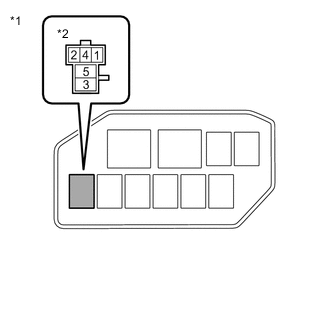
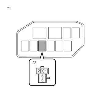
*1 No. 2 Relay Block Assembly *2 FAN NO. 1 Relay Measure the voltage according to the value(s) in the table below.
Standard Voltage Tester Connection Condition Specified Condition 2 (FAN NO. 1 relay) - Body ground Remote climate control system on 11 to 14 V 5 (FAN NO. 1 relay) - Body ground Remote climate control system on 11 to 14 V Result Proceed to OK NG
OK
REPAIR OR REPLACE HARNESS OR CONNECTOR (FAN NO. 1 RELAY - BODY GROUND)
NG
-
-
INSPECT IG-B RELAY
-
Remove the IG-B relay from the No. 2 relay block assembly.
-
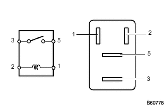
Measure the resistance according to the value(s) in the table below.
Standard Resistance Tester Connection Condition Specified Condition 3 - 5 Auxiliary battery voltage applied between terminals 1 and 2 Below 1 Ω 3 - 5 Auxiliary battery voltage not applied between terminals 1 and 2 10 kΩ or higher Result Proceed to OK NG
NG
REPLACE IG-B RELAY
OK
-
-
CHECK HARNESS AND CONNECTOR (IG-B RELAY POWER SOURCE CIRCUIT)
-
Remove the IG-B relay from the No. 2 relay block assembly.
-
*1 No. 2 Relay Block Assembly *2 IG-B Relay Measure the voltage according to the value(s) in the table below.
Standard Voltage Tester Connection Condition Specified Condition 3 (IG-B relay) - Body ground Always 11 to 14 V Result Proceed to OK NG
NG
REPAIR OR REPLACE HARNESS OR CONNECTOR (IG-B RELAY - AUXILIARY BATTERY)
OK
-
-
CHECK HARNESS AND CONNECTOR (IG-B RELAY - FAN NO. 1 RELAY)
-
Remove the IG-B relay and FAN NO. 1 relay from the No. 2 relay block assembly.
-
Measure the resistance according to the value(s) in the table below.
Standard Resistance Tester Connection Condition Specified 5 (IG-B relay) - 2 (FAN NO. 1 relay) Always Below 1 Ω 5 (IG-B relay) - 5 (FAN NO. 1 relay) Always Below 1 Ω 5 (IG-B relay), 2 (FAN NO. 1 relay) or 5 (FAN NO. 1 relay) - Body ground Always 10 kΩ or higher Result Proceed to OK NG
NG
REPLACE NO.2 RELAY BLOCK ASSEMBLY
OK
-
-
CHECK HARNESS AND CONNECTOR (IG-B RELAY - BODY GROUND)
-
Remove the IG-B relay from the No. 2 relay block assembly.
-
Measure the resistance according to the value(s) in the table below.
Standard Resistance Tester Connection Condition Specified Condition 1 (IG-B relay) - Body ground Always Below 1 Ω Result Proceed to OK NG
OK
REPAIR OR REPLACE HARNESS OR CONNECTOR (IG-B RELAY - CERTIFICATION ECU (SMART KEY ECU ASSEMBLY))
NG
REPAIR OR REPLACE HARNESS OR CONNECTOR
-
-
INSPECT FAN NO. 1 RELAY
-
Inspect the FAN NO. 1 relay.
Result Proceed to OK NG
OK
REPAIR OR REPLACE HARNESS OR CONNECTOR (COOLING FAN MOTOR RH AND COOLING FAN MOTOR LH - FAN NO. 1 RELAY)
NG
REPLACE FAN NO. 1 RELAY
-