PURGE VALVE INSTALLATION
PROCEDURE
-
INSTALL PURGE VALVE (PURGE VSV)
-
Install the purge valve (purge VSV) to the No. 3 water by-pass pipe with the screw.
- Torque:
- 3.4 N*m { 35 kgf*cm, 30 in.*lbf }
-
Install the purge valve (purge VSV) with No. 3 water by-pass pipe to the camshaft housing sub-assembly with the bolt.
- Torque:
- 28 N*m { 286 kgf*cm, 21 ft.*lbf }
-
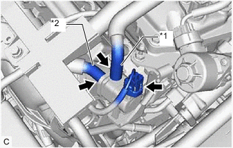
*1 No. 1 Fuel Vapor Feed Hose *2 No. 2 Fuel Vapor Feed Hose Connect the No. 2 fuel vapor feed hose to the purge valve (purge VSV).
-
Connect the No. 1 fuel vapor feed hose to the purge valve (purge VSV).
-
Connect the purge valve (purge VSV) connector.
-
-
CONNECT NO. 9 WATER BY-PASS HOSE
-
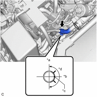
*a Up *b LH *c Paint Mark *d 180° Connect the No. 9 water by-pass hose to the No. 3 water by-pass pipe and slide the clip to secure it.
Tech Tips
Engage the clip within the area shown in the illustration.
-
-
CONNECT NO. 8 WATER BY-PASS HOSE
-
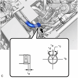
*a Up *b LH *c Paint Mark *d 60° *e 2 to 7 mm (0.0787 to 0.276 in.) Connect the No. 8 water by-pass hose to the No. 3 water by-pass pipe and slide the clip to secure it.
Tech Tips
Engage the clip within the area shown in the illustration.
-
-
INSTALL EGR PIPE ASSEMBLY
-
ADD ENGINE COOLANT (for Engine)
-
INSPECT FOR COOLANT LEAK (for Engine)
-
INSTALL REAR ENGINE UNDER COVER LH
-
INSTALL NO. 1 ENGINE COVER SUB-ASSEMBLY