STOP LIGHT SWITCH INSTALLATION
CAUTION / NOTICE / HINT
Tech Tips
-
Use the same procedure for RHD and LHD vehicles.
-
The procedure listed below is for LHD vehicles.
PROCEDURE
-
INSTALL STOP LIGHT SWITCH MOUNTING ADJUSTER
-
Engage the claws to install a new stop light switch mounting adjuster.
-
-
INSTALL STOP LIGHT SWITCH ASSEMBLY
-
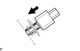
Insert the stop light switch assembly until the threaded sleeve hits the pedal.
Note
-
When inserting the stop light switch assembly, support the pedal from behind so that the pedal is not pushed in.
-
Do not depress or support the brake pedal.
-
-

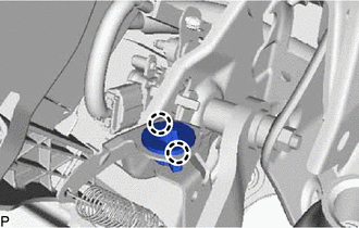
Turn Turn the stop light switch assembly a quarter turn clockwise to install the stop light switch assembly.
Torque 1.5 N*m (15 kgf*cm, 13 in.*lbf) or less Note
-
When inserting the stop light switch assembly, support the pedal from behind so that the pedal is not pushed in.
-
Do not depress or support the brake pedal.
-
-
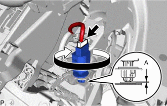
Check the protrusion of the plunger.
Protrusion of Plunger Area Measurement A 0.5 to 2.6 mm (0.0197 to 0.102 in.) If the protrusion is not as specified, recheck the switch installation and inspect brake pedal adjustment if necessary.
Note
-
When inserting the stop light switch assembly, support the pedal from behind so that the pedal is not pushed in.
-
Do not depress or support the brake pedal.
-
-
Connect the connector.
-
Check that the stop light does not come on when the brake pedal is not depressed.
-
-
INSTALL NO. 1 INSTRUMENT PANEL UNDER COVER SUB-ASSEMBLY