REAR COMBINATION LIGHT ASSEMBLY INSPECTION
PROCEDURE
-
INSPECT REAR COMBINATION LIGHT ASSEMBLY LH
-
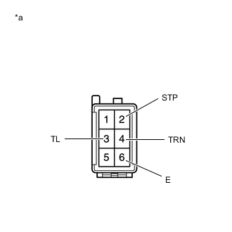
*a Component without harness connected
(Rear Combination Light Assembly LH)
Apply auxiliary battery voltage to the rear combination light assembly LH and check that the light comes on.
OK Condition Specified Condition Auxiliary battery positive (+) → Terminal 4 (TRN)
Auxiliary battery negative (-) → Terminal 6 (E)
Rear turn signal light comes on Auxiliary battery positive (+) → Terminal 3 (TL)
Auxiliary battery negative (-) → Terminal 6 (E)
Taillight comes on Auxiliary battery positive (+) → Terminal 2 (STP)
Auxiliary battery negative (-) → Terminal 6 (E)
Stop light comes on Tech Tips
If the result is not as specified, inspect the rear combination light cord LH or replace the combination light lens and body LH.
-
-
INSPECT REAR COMBINATION LIGHT ASSEMBLY RH
-
*a Component without harness connected
(Rear Combination Light Assembly RH)
Apply auxiliary battery voltage to the rear combination light assembly RH and check that the light comes on.
OK Condition Specified Condition Auxiliary battery positive (+) → Terminal 4 (TRN)
Auxiliary battery negative (-) → Terminal 6 (E)
Rear turn signal light comes on Auxiliary battery positive (+) → Terminal 3 (TL)
Auxiliary battery negative (-) → Terminal 6 (E)
Taillight comes on Auxiliary battery positive (+) → Terminal 2 (STP)
Auxiliary battery negative (-) → Terminal 6 (E)
Stop light comes on Tech Tips
If the result is not as specified, inspect the rear combination light cord RH or replace the combination light lens and body RH.
-
-
INSPECT REAR COMBINATION LIGHT CORD LH
-
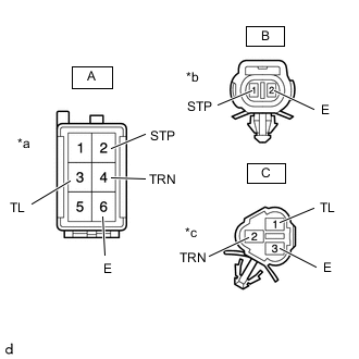
*a Front view of wire harness connector
(to Floor Wire Connector)
*b Front view of wire harness connector
(to Rear Combination Light Connector)
*c Front view of wire harness connector
(to Rear Combination Light Connector)
Measure the resistance according to the value(s) in the table below.
Standard Resistance Tester Connection Condition Specified Condition A-2 (STP) - B-1 (STP) Always Below 1 Ω A-3 (TL) - C-1 (TL) Always Below 1 Ω A-4 (TRN) - C-2 (TRN) Always Below 1 Ω A-6 (E) - B-2 (E) Always Below 1 Ω A-6 (E) - C-3 (E) Always Below 1 Ω Tech Tips
If the result is not as specified, replace the rear combination light cord LH.
-
-
INSPECT REAR COMBINATION LIGHT CORD RH
-
*a Front view of wire harness connector
(to Floor Wire Connector)
*b Front view of wire harness connector
(to Rear Combination Light Connector)
*c Front view of wire harness connector
(to Rear Combination Light Connector)
Measure the resistance according to the value(s) in the table below.
Standard Resistance Tester Connection Condition Specified Condition A-2 (STP) - B-1 (STP) Always Below 1 Ω A-3 (TL) - C-1 (TL) Always Below 1 Ω A-4 (TRN) - C-2 (TRN) Always Below 1 Ω A-6 (E) - B-2 (E) Always Below 1 Ω A-6 (E) - C-3 (E) Always Below 1 Ω Tech Tips
If the result is not as specified, replace the rear combination light cord RH.
-