LIGHTING SYSTEM Hazard Warning Switch Circuit
DESCRIPTION
When the combination meter receives a hazard warning signal switch signal, the flasher IC turns on and hazard control is performed.
WIRING DIAGRAM
CAUTION / NOTICE / HINT
Note
When replacing the combination meter assembly, make sure to replace it with a new one.
PROCEDURE
-
READ VALUE USING GTS (HAZARD FLASHER SWITCH)
-
Using the GTS, read the Data List.
Body Electrical > Combination Meter > Data ListTester Display Measurement Item Range Normal Condition Diagnostic Note Hazard Flasher Switch Hazard warning signal switch signal ON or OFF ON: Hazard switch on
OFF: Hazard switch off
-
Body Electrical > Combination Meter > Data ListTester Display Hazard Flasher Switch Result Proceed to OK NG
OK 
PROCEED TO NEXT SUSPECTED AREA SHOWN IN PROBLEM SYMPTOMS TABLE Click here
NG 
-
-
INSPECT HAZARD WARNING SWITCH
-
Remove the hazard warning switch.
-
Inspect the hazard warning switch.
Result Proceed to OK NG
NG
REPLACE HAZARD WARNING SIGNAL SWITCH Click here
OK
-
-
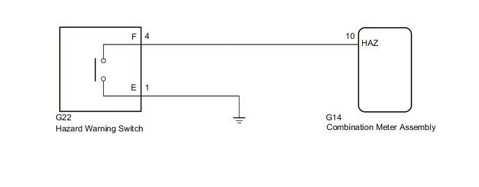
CHECK HARNESS AND CONNECTOR (HAZARD WARNING SWITCH - COMBINATION METER ASSEMBLY AND BODY GROUND)
-
Disconnect the G22 hazard warning switch connector.
-
Disconnect the G14 combination meter assembly connector.
-
Measure the resistance according to the value(s) in the table below.
Standard Resistance Tester Connection Condition Specified Condition G14-10 (HAZ) - G22-4 (F) Always Below 1 Ω G22-4 (F) - Body ground Always Below 1 Ω G14-10 (HAZ) or G22-4 (F) - Body ground Always 10 kΩ or higher Result Proceed to OK NG
OK
REPLACE COMBINATION METER ASSEMBLY Click here
NG
REPAIR OR REPLACE HARNESS OR CONNECTOR
-