LIGHTING SYSTEM Daytime Running Light Relay Circuit
DESCRIPTION
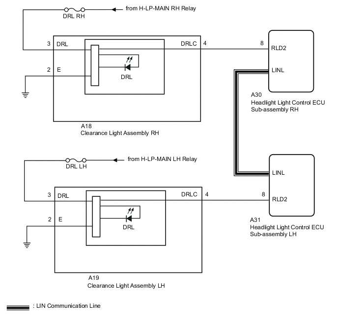
The illumination of the daytime running light (clearance light assembly) or clearance light is controlled by the headlight light control ECU sub-assembly.
WIRING DIAGRAM
CAUTION / NOTICE / HINT
Note
Inspect the fuses for circuits related to this system before performing the following inspection procedure.
PROCEDURE
-
PERFORM ACTIVE TEST USING GTS (DAYTIME RUNNING LIGHT)
-
Using the GTS, perform the Active Test.
Body Electrical > HL AutoLeveling > Active TestTester Display Measurement Item Control Range Diagnostic Note Clearance Light Illuminates cornering lights ON or OFF - Daytime Running Light Illuminates daytime running lights ON or OFF -
Body Electrical > HL AutoLeveling > Active TestTester Display Clearance Light
Body Electrical > HL AutoLeveling > Active TestTester Display Daytime Running Light Result Result Proceed to The Active Test is performed normally A The Active Test is not performed normally for the right side light only B The Active Test is not performed normally for the left side light only C
A 
PROCEED TO NEXT SUSPECTED AREA SHOWN IN PROBLEM SYMPTOMS TABLE Click here
C 
CHECK HARNESS AND CONNECTOR (CLEARANCE LIGHT ASSEMBLY LH - BATTERY AND BODY GROUND) Click here
B 
-
-
CHECK HARNESS AND CONNECTOR (CLEARANCE LIGHT ASSEMBLY RH - BATTERY AND BODY GROUND)
-
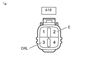
*a Front view of wire harness connector
(to Clearance Light Assembly RH )
Disconnect the clearance light assembly RH connector.
-
Measure the voltage according to the value(s) in the table below.
Standard Voltage Tester Connection Switch Condition Specified Condition A18-3 (DRL) - Body ground Power switch on (IG) 11 to 14 V -
Measure the resistance according to the value(s) in the table below.
Standard Resistance Tester Connection Condition Specified Condition A18-2 (E) - Body ground Always Below 1 Ω Result Proceed to OK NG
NG
REPAIR OR REPLACE HARNESS OR CONNECTOR
OK
-
-
CHECK HARNESS AND CONNECTOR (HEADLIGHT LIGHT CONTROL ECU SUB-ASSEMBLY RH - CLEARANCE LIGHT ASSEMBLY RH)
-
Disconnect the A30 headlight light control ECU sub-assembly RH connector.
-
Disconnect the A18 clearance light assembly RH connector.
-
Measure the resistance according to the value(s) in the table below.
Standard Resistance Tester Connection Condition Specified Condition A30-8 (RLD2) - A18-4 (DRLC) Always Below 1 Ω A30-8 (RLD2) or A18-4 (DRLC) - Body ground Always 10 kΩ or higher Result Proceed to OK NG
NG
REPAIR OR REPLACE HARNESS OR CONNECTOR
OK
-
-
INSPECT CLEARANCE LIGHT ASSEMBLY RH
-
Remove the clearance light assembly RH.
-
Inspect the clearance light assembly RH.
Result Proceed to OK NG
OK
REPLACE HEADLIGHT LIGHT CONTROL ECU SUB-ASSEMBLY RH Click here
NG
REPLACE CLEARANCE LIGHT ASSEMBLY RH Click here
-
-
CHECK HARNESS AND CONNECTOR (CLEARANCE LIGHT ASSEMBLY LH - BATTERY AND BODY GROUND)
-
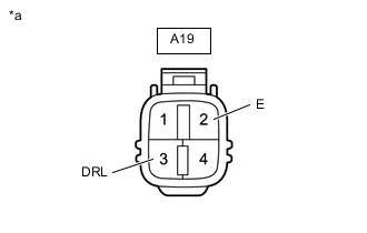
*a Front view of wire harness connector
(to Clearance Light Assembly LH )
Disconnect the clearance light assembly LH connector.
-
Measure the voltage according to the value(s) in the table below.
Standard Voltage Tester Connection Switch Condition Specified Condition A19-3 (DRL) - Body ground Power switch on (IG) 11 to 14 V -
Measure the resistance according to the value(s) in the table below.
Standard Resistance Tester Connection Condition Specified Condition A19-2 (E) - Body ground Always Below 1 Ω Result Proceed to OK NG
NG
REPAIR OR REPLACE HARNESS OR CONNECTOR
OK
-
-
CHECK HARNESS AND CONNECTOR (HEADLIGHT LIGHT CONTROL ECU ASSEMBLY LH - CLEARANCE LIGHT ASSEMBLY LH)
-
Disconnect the A31 headlight light control ECU sub-assembly LH connector.
-
Disconnect the A19 clearance light assembly LH connector.
-
Measure the resistance according to the value(s) in the table below.
Standard Resistance Tester Connection Condition Specified Condition A31-8 (RLD2) - A19-4 (DRLC) Always Below 1 Ω A31-8 (RLD2) or A19-4 (DRLC) - Body ground Always 10 kΩ or higher Result Proceed to OK NG
NG
REPAIR OR REPLACE HARNESS OR CONNECTOR
OK
-
-
INSPECT CLEARANCE LIGHT ASSEMBLY LH
-
Remove the clearance light assembly LH.
-
Inspect the clearance light assembly LH.
Result Proceed to OK NG
OK
REPLACE HEADLIGHT LIGHT CONTROL ECU SUB-ASSEMBLY LH Click here
NG
REPLACE CLEARANCE LIGHT ASSEMBLY LH Click here
-