LIGHTING SYSTEM TERMINALS OF ECU
-
CHECK INSTRUMENT PANEL JUNCTION BLOCK ASSEMBLY, MAIN BODY ECU (MULTIPLEX NETWORK BODY ECU)
-
Remove the main body ECU (multiplex network body ECU) from the instrument panel junction block assembly.
for LHD:
for RHD:
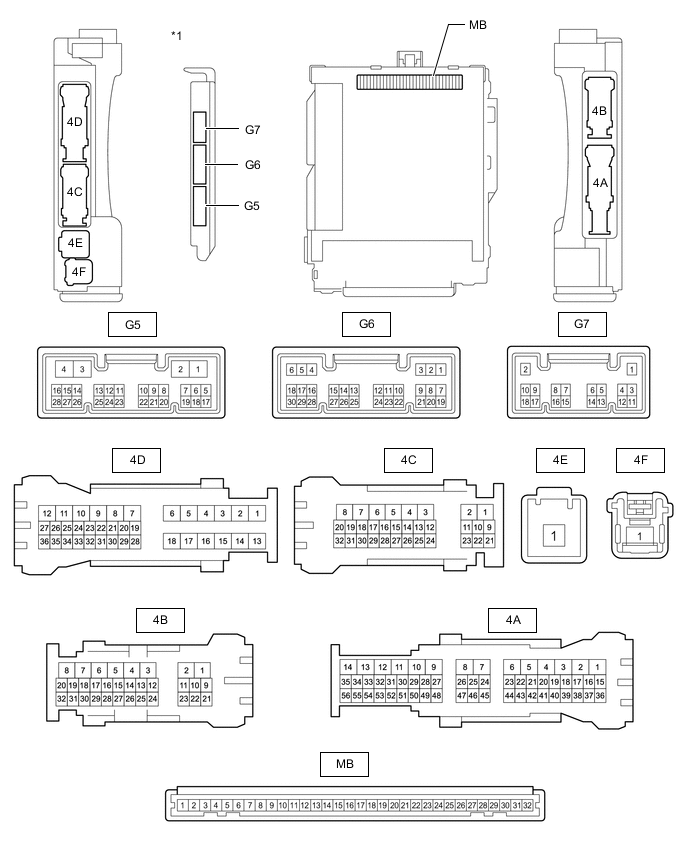
*1 Main Body ECU (Multiplex Network Body ECU) - - -
Connect the instrument panel junction block assembly connectors.
-
Measure the voltage and resistance according to the value(s) in the table below.
Terminal No. (Symbol) Wiring Color Terminal Description Condition Specified Condition MB-32 (IG) - Body ground - Ignition power supply Power switch off Below 1 V Power switch on (IG) 11 to 14 V MB-31 (BECU) - Body ground - Battery power supply Power switch off 11 to 14 V MB-30 (ACC) - Body ground - ACC power supply Power switch off Below 1 V Power switch on (ACC) 11 to 14 V MB-11 (GND1) - Body ground - Ground Always Below 1 Ω If the result is not as specified, there may be a malfunction in the wire harness or instrument panel junction block assembly.
-
Install the main body ECU (multiplex network body ECU).
for LHD:
for RHD:
-
Measure the voltage according to the value(s) in the table below.
Terminal No. (Symbol) Wiring Color Terminal Description Condition Specified Condition G6-1 (DIM) - Body ground V - Body ground H-LP-MAIN RH relay drive output Power switch off 11 to 14 V Power switch on (IG) Below 1 V G6-8 (A) - Body ground G - Body ground Headlight dimmer switch AUTO signal input Headlight dimmer switch not in AUTO position 11 to 14 V Headlight dimmer switch in AUTO position Below 1 V G6-10 (HF) - Body ground R - Body ground Headlight dimmer switch high flash signal input Headlight dimmer switch not in high flash position 11 to 14 V Headlight dimmer switch in high flash position Below 1 V G6-12 (HEAD) - Body ground P - Body ground Headlight dimmer switch head signal input Headlight dimmer switch not in head position 11 to 14 V Headlight dimmer switch in head position Below 1 V G6-19 (CLTB) - G6-21 (CLTE) Y - BR Automatic light control sensor power supply output Headlight dimmer switch in AUTO position 11 to 14 V G6-22 (TAIL) - Body ground L - Body ground Headlight dimmer switch tail signal input Headlight dimmer switch in neither tail nor head position 11 to 14 V Headlight dimmer switch in tail or head position Below 1 V G6-24 (HU) - Body ground W - Body ground Headlight dimmer switch high signal input Headlight dimmer switch in low position 11 to 14 V Headlight dimmer switch in high position Below 1 V G6-23 (RFOG) - Body ground V - Body ground Rear fog light switch input Rear fog light switch off 11 to 14 V Rear fog light switch on Below 1 V 4C-29 (HRLY) - Body ground P - Body ground H-LP-MAIN RH relay drive output Power switch off 11 to 14 V Power switch on (IG) Below 1 V 4D-12 (RFGO) - Body ground P - Body ground Rear fog light signal output Headlight dimmer switch in tail or head position and rear fog light switch off 11 to 14 V Headlight dimmer switch in tail or head position and rear fog light switch on Below 1 V -
Measure the voltage and check the waveform between each connector terminal using an oscilloscope according to the value(s) in the table below.
Terminal No. (Symbol) Wiring Color Terminal Description Condition Specified Condition G6-20 (CLTS) - Body ground SB - Body ground Automatic light control sensor signal input Power switch on (IG), headlight dimmer switch in AUTO position and automatic light control sensor covered with a hand → Automatic light control sensor exposed to ambient light Pulse generation
(waveform varies depending on light volume)
G6-6 (FLCY) - Body ground*1 P - Body ground Front door courtesy light switch LH signal Front door LH open Below 1 V Front door LH closed Pulse generation G6-27 (FRCY) - Body ground*2 L - Body ground Front door courtesy light switch RH signal Front door RH open Below 1 V Front door RH closed Pulse generation *1: for LHD
*2: for RHD
-
-
CHECK COMBINATION METER ASSEMBLY
-
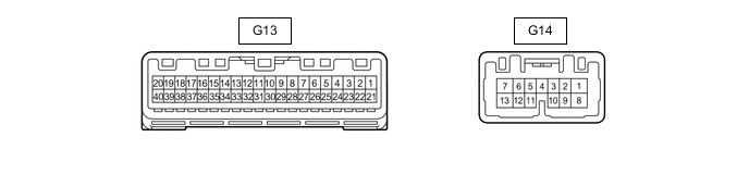
Disconnect the G13 and G14 combination meter connectors.
-
Measure the resistance and voltage according to the value(s) in the table below.
Terminal No. (Symbol) Wiring Color Terminal Description Condition Specified Condition G13-22 (B) - Body ground GR - Body ground Battery power supply Power switch off 11 to 14 V G13-21 (IG+) - Body ground BE - Body ground Ignition power supply Power switch off Below 1 V Power switch on (IG) 9.5 to 14 V G14-1 (B) - Body ground P - Body ground Battery power supply Power switch off 11 to 14 V G14-10 (HAZ) - Body ground R - Body ground Hazard warning signal switch signal input Hazard warning signal switch off 11 to 14 V Hazard warning signal switch on Below 1 V G13-28 (ES) - Body ground BR - Body ground Ground Always Below 1 Ω -
Reconnect the G13 and G14 combination meter connectors.
-
Measure the voltage according to the value(s) in the table below.
Terminal No. (Symbol) Wiring Color Terminal Description Condition Specified Condition G14-5 (ER) - Body ground G - Body ground Turn signal switch (right turn position) signal input Power switch on (IG) Turn signal switch off 11 to 14 V Power switch on (IG) Turn signal switch in right turn position Below 1 V G14-11 (EL) - Body ground SB - Body ground Turn signal switch (left turn position) signal input Power switch on (IG) Turn signal switch off 11 to 14 V Power switch on (IG) Turn signal switch in left turn position Below 1 V G14-9 (SW) - Body ground V - Body ground Turn signal switch (full turn position) signal input Power switch on (IG) Turn signal switch off 11 to 14 V Power switch on (IG) Turn signal switch in full turn position Below 1 V G14-6 (LR) - Body ground L - Body ground RH turn signal light signal output Power switch on (IG) RH turn signal light off Below 1 V Power switch on (IG) RH turn signal light blinking Below 1 V ←→ 11 to 14 V G14-12 (LL) - Body ground B - Body ground LH turn signal light signal output Power switch on (IG) LH turn signal light off Below 1 V Power switch on (IG) RH turn signal light blinking Below 1 V ←→ 11 to 14 V G14-7 (TRNR) - Body ground GR - Body ground RH turn signal light signal output Power switch on (IG) RH turn signal light off Below 1 V Power switch on (IG) RH turn signal light blinking Below 1 V ←→ 11 to 14 V G14-13 (TRNL) - Body ground Y - Body ground LH turn signal light signal output Power switch on (IG) LH turn signal light off Below 1 V Power switch on (IG) RH turn signal light blinking Below 1 V ←→ 11 to 14 V
-
-
HEADLIGHT LIGHT CONTROL ECU SUB-ASSEMBLY LH
-
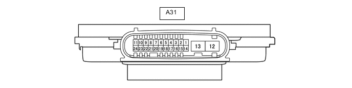
Disconnect the A31 headlight light control ECU sub-assembly LH connector.
-
Measure the resistance and voltage according to the value(s) in the table below.
Terminal No. (Symbol) Wiring Color Terminal Description Condition Specified Condition A31-4 (IG) - Body ground LG - Body ground Ignition power supply Power switch off Below 1 V Power switch on (IG) 11 to 14 V A31-13 (ECUB) - Body ground B - Body ground Power supply Headlight off Below 1 V Headlight on 11 to 14 V A31-12 (GND) - Body ground W-B - Body ground Ground Always Below 1 Ω -
Reconnect the A31 headlight light control ECU sub-assembly LH connector.
Tech Tips
Since the headlight light control ECU sub-assembly LH uses waterproof connectors, the voltage, resistance and waveform cannot be checked directly. The voltage, resistance and waveform are indicated for reference only.
-
Measure the voltage and pulse according to the value(s) in the table below.
Terminal No. (Symbol) Wiring Color Terminal Description Condition Specified Condition A31-8 (RLD2) - Body ground G - Body ground Daytime running light system drive output Daytime running light on No pulse Daytime running light off Pulse generation A31-16 (SBR) - A31-15 (SGR) BR - P Rear height control sensor power supply Power switch on (IG) Approximately 5 V A31-17 (SHRL) - A31-15 (SGR) Y - P Rear height control sensor signal input (No passengers, no luggage, vehicle not moving) Approximately 2.5 V
(vehicle level) (value decreases as the front of the vehicle is raised)
A31-20 (LINL) - Body ground SB - Body ground LIN communication Power switch on (IG) Below 1 V
-
-
HEADLIGHT LIGHT CONTROL ECU SUB-ASSEMBLY RH
-
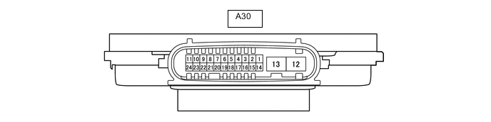
Disconnect the A30 headlight light control ECU sub-assembly RH connector.
-
Measure the resistance and voltage according to the value(s) in the table below.
Terminal No. (Symbol) Wiring Color Terminal Description Condition Specified Condition A30-4 (IG) - Body ground LG - Body ground Ignition power supply Power switch off Below 1 V Power switch on (IG) 11 to 14 V A30-13 (ECUB) - Body ground L - Body ground Power supply Headlight off Below 1 V Headlight on 11 to 14 V A30-12 (GND) - Body ground W-B - Body ground Ground Always Below 1 Ω -
Reconnect the A30 headlight light control ECU sub-assembly RH connector.
Tech Tips
Since the headlight light control ECU sub-assembly RH uses waterproof connectors, the voltage, resistance and waveform cannot be checked directly. The voltage, resistance and waveform are indicated for reference only.
-
Measure the voltage and pulse according to the value(s) in the table below.
Terminal No. (Symbol) Wiring Color Terminal Description Condition Specified Condition A30-8 (RLD2) - Body ground Y - Body ground Daytime running light system drive output Daytime running light on No pulse Daytime running light off Pulse generation A30-20 (LINL) - Body ground SB - Body ground LIN communication Power switch on (IG) Below 1 V
-