POWER MIRROR CONTROL SYSTEM TERMINALS OF ECU
-
CHECK OUTER MIRROR CONTROL ECU ASSEMBLY LH

-
Disconnect the L10 outer mirror control ECU assembly connector.
-
Measure the voltage and resistance according to the value(s) in the table below.
Tester Connection Wiring Color Terminal Description Condition Specified Condition L10-5 (SIG) - L10-7 (GND) Y - BR Power source Power switch on (IG) 11 to 14 V Power switch off Below 1 V L10-6 (CPUB) - L10-7 (GND) BR - BR (for LHD)
BE - BR (for RHD)
Power source Power switch off 11 to 14 V L10-14 (BDR) - L10-7 (GND) SB - BR Power source Power switch off 11 to 14 V L10-7 (GND) - Body ground BR - Body ground Ground Always Below 1 Ω -
Reconnect the L10 outer mirror control ECU assembly connector.
-
Measure the voltage according to the value(s) in the table below.
Tester Connection Wiring Color Terminal Description Condition Specified Condition z11-3 (MR) - Body ground G - Body ground Power retract mirror motor drive voltage
-
Power switch on (ACC)
-
Outer rear view mirror assembly being retracted
11 to 14 V
-
Power switch on (ACC)
-
Outer rear view mirror assembly stopped
Below 1 V z11-11 (MF) - Body ground L - Body ground Power retract mirror motor drive voltage
-
Power switch on (ACC)
-
Outer rear view mirror assembly returning
11 to 14 V
-
Power switch on (ACC)
-
Outer rear view mirror assembly stopped
Below 1 V z11-1 (MV) - Body ground W - Body ground Mirror motor drive voltage
-
Power switch on (ACC)
-
Mirror surface stopped
Below 1 V
-
Power switch on (ACC)
-
Mirror surface moving downward or left
Below 1 V
-
Power switch on (ACC)
-
Mirror surface moving upward
11 to 14 V z11-9 (MH) - Body ground R - Body ground Mirror motor drive voltage
-
Power switch on (ACC)
-
Mirror surface stopped
Below 1 V
-
Power switch on (ACC)
-
Mirror surface moving upward or right
Below 1 V
-
Power switch on (ACC)
-
Mirror surface moving left
11 to 14 V z11-10 (M+) - Body ground B - Body ground Mirror motor drive voltage
-
Power switch on (ACC)
-
Mirror surface stopped
Below 1 V
-
Power switch on (ACC)
-
Mirror surface moving upward or left
Below 1 V
-
Power switch on (ACC)
-
Mirror surface moving downward or right
11 to 14 V z11-4 (+) - z11-12 (-) BR-W - B-R Mirror heater drive voltage
-
Power switch on (IG)
-
Rear window defogger switch on
11 to 14 V
-
Power switch on (IG)
-
Rear window defogger switch off
Below 1 V z11-5 (VC) - z11-14 (E1) SB - GR Mirror position sensor power supply Power switch on (IG) 4.5 to 5.5 V Power switch off Below 1 V z11-6 (VSRL) - Body ground V - Body ground Vertical direction position sensor signal
-
Power switch on (ACC)
-
Mirror surface moving upward or downward
Changes within range of 0 to 5 V z11-13 (HSRL) - Body ground LG - Body ground Horizontal direction position sensor signal
-
Power switch on (ACC)
-
Mirror surface moving left or right
Changes within range of 0 to 5 V L10-2 (M1) - L10-7 (GND)*1 BE - BR Seat memory switch M1 signal
-
Power switch on (IG)
-
Seat memory switch M1 off
11 to 14 V
-
Power switch on (IG)
-
Seat memory switch M1 on
Below 1 V L10-3 (M2) - L10-7 (GND)*1 GR - BR Seat memory switch M2 signal
-
Power switch on (IG)
-
Seat memory switch M2 off
11 to 14 V
-
Power switch on (IG)
-
Seat memory switch M2 on
Below 1 V L10-1 (MM) - L10-7 (GND)*1 LG - BR Seat memory switch SET signal
-
Power switch on (IG)
-
Seat memory switch SET off
11 to 14 V
-
Power switch on (IG)
-
Seat memory switch SET on
Below 1 V
-
*1: for LHD
-
-
-
CHECK OUTER MIRROR CONTROL ECU ASSEMBLY RH

-
Disconnect the L1 outer mirror control ECU assembly connector.
-
Measure the voltage and resistance according to the value(s) in the table below.
Tester Connection Wiring Color Terminal Description Condition Specified Condition L1-5 (SIG) - L1-7 (GND) G - BR Power source Power switch on (IG) 11 to 14 V Power switch off Below 1 V L1-6 (CPUB) - L1-7 (GND) GR - BR Power source Power switch off 11 to 14 V L1-14 (BDR) - L1-7 (GND) R - BR Power source Power switch off 11 to 14 V L1-7 (GND) - Body ground BR - Body ground Ground Always Below 1 Ω -
Reconnect the L1 outer mirror control ECU assembly connector.
-
Measure the voltage according to the value(s) in the table below.
Tester Connection Wiring Color Terminal Description Condition Specified Condition z12-3 (MR) - Body ground G - Body ground Power retract mirror motor drive voltage
-
Power switch on (ACC)
-
Outer rear view mirror assembly being retracted
11 to 14 V
-
Power switch on (ACC)
-
Outer rear view mirror assembly stopped
Below 1 V z12-11 (MF) - Body ground L - Body ground Power retract mirror motor drive voltage
-
Power switch on (ACC)
-
Outer rear view mirror assembly returning
11 to 14 V
-
Power switch on (ACC)
-
Outer rear view mirror assembly stopped
Below 1 V z12-1 (MV) - Body ground W - Body ground Mirror motor drive voltage
-
Power switch on (ACC)
-
Mirror surface stopped
Below 1 V
-
Power switch on (ACC)
-
Mirror surface moving downward or left
Below 1 V
-
Power switch on (ACC)
-
Mirror surface moving upward
11 to 14 V z12-9 (MH) - Body ground R - Body ground Mirror motor drive voltage
-
Power switch on (ACC)
-
Mirror surface stopped
Below 1 V
-
Power switch on (ACC)
-
Mirror surface moving upward or right
Below 1 V
-
Power switch on (ACC)
-
Mirror surface moving left
11 to 14 V z12-10 (M+) - Body ground B - Body ground Mirror motor drive voltage
-
Power switch on (ACC)
-
Mirror surface stopped
Below 1 V
-
Power switch on (ACC)
-
Mirror surface moving upward or left
Below 1 V
-
Power switch on (ACC)
-
Mirror surface moving downward or right
11 to 14 V z12-4 (+) - z12-12 (-) BR-W - B-R Mirror heater drive voltage
-
Power switch on (IG)
-
Rear window defogger switch on
11 to 14 V
-
Power switch on (IG)
-
Rear window defogger switch off
Below 1 V z12-5 (VC) - z12-14 (E1) SB - GR Mirror position sensor power supply Power switch on (IG) 4.75 to 5.25 V Power switch off Below 1 V z12-6 (VSSR) - Body ground V - Body ground Vertical direction position sensor signal
-
Power switch on (ACC)
-
Mirror surface moving upward or downward
Changes within range of 0 to 5 V z12-13 (HSSR) - Body ground LG - Body ground Horizontal direction position sensor signal
-
Power switch on (ACC)
-
Mirror surface moving left or right
Changes within range of 0 to 5 V L1-2 (M1) - L1-7 (GND)*1 P - BR Seat memory switch M1 signal
-
Power switch on (IG)
-
Seat memory switch M1 off
11 to 14 V
-
Power switch on (IG)
-
Seat memory switch M1 on
Below 1 V L1-3 (M2) - L1-7 (GND)*1 L - BR Seat memory switch M2 signal
-
Power switch on (IG)
-
Seat memory switch M2 off
11 to 14 V
-
Power switch on (IG)
-
Seat memory switch M2 on
Below 1 V L2-1 (MM) - L1-7 (GND)*1 SB - BR Seat memory switch SET signal
-
Power switch on (IG)
-
Seat memory switch SET off
11 to 14 V
-
Power switch on (IG)
-
Seat memory switch SET on
Below 1 V
-
*1: for RHD
-
-
-
CHECK INSTRUMENT PANEL JUNCTION BLOCK ASSEMBLY (MAIN BODY ECU (MULTIPLEX NETWORK BODY ECU))
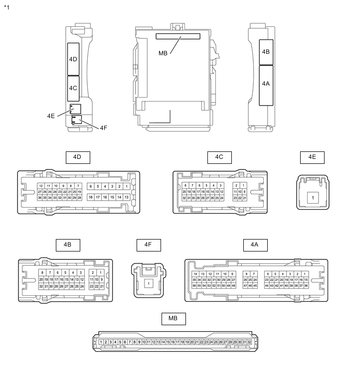
*1 Instrument Panel Junction Block Assembly - - 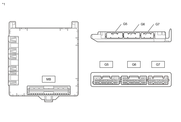
*1 Main Body ECU (Multiplex Network Body ECU) - -
-
Measure the voltage and pulse according to the value(s) in the table below.
Tester Connection Wiring Color Terminal Description Condition Specified Condition G7-4 (MIRB) -G7-6 (MIRE) L - BE Mirror surface adjust switch signal
-
Power switch on (ACC)
-
Mirror surface adjust switch up
Below 1.7 V
-
Power switch on (ACC)
-
Mirror surface adjust switch right
Below 2.7 V
-
Power switch on (ACC)
-
Mirror surface adjust switch down
Below 3.5 V
-
Power switch on (ACC)
-
Mirror surface adjust switch left
Below 4 V
-
Power switch on (ACC)
-
Mirror surface adjust switch off
3.8 to 5 V G7-5 (MIRS) - G7-6 (MIRE) P - BE Mirror select switch signal
-
Power switch on (ACC)
-
Mirror select switch L
Below 2 V
-
Power switch on (ACC)
-
Mirror select switch R
Below 1 V
-
Power switch on (ACC)
-
Mirror select switch off
3.8 to 5 V G5-14 (RET) - 4B-7 (GND1) GR - W-B Mirror retract switch signal
-
Power switch on (ACC)
-
Mirror retract switch not in return position
Pulse generation (See waveform 1 or 2)
-
Power switch on (ACC)
-
Mirror retract switch in return position
Below 1 V G5-15 (RTR) - 4B-7 (GND1) V - W-B Mirror retract switch signal
-
Power switch on (ACC)
-
Mirror retract switch not in retract position
Pulse generation (See waveform 1 or 2)
-
Power switch on (ACC)
-
Mirror retract switch in retract position
Below 1 V -
-
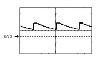
Using an oscilloscope, check waveform 1.
Waveform 1 (Reference) Item Content Terminal No. (Symbol) G5-14 (RET) or G5-15 (RTR) - 4B-7 (GND1) Tool Setting 5 V/DIV., 20 ms/DIV. Condition
-
Power switch on (ACC)
-
Mirror retract switch not in retract position
-
-
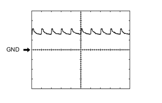
Using an oscilloscope, check waveform 2.
Waveform 2 (Reference) Item Content Terminal No. (Symbol) G5-14 (RET) or G5-15 (RTR) - 4B-7 (GND1) Tool Setting 5 V/DIV., 20 ms/DIV. Condition
-
Power switch on (ACC)
-
Mirror retract switch not in retract position
-
-