REAR DOOR ADJUSTMENT

CAUTION / NOTICE / HINT
Tech Tips
-
Use the same procedure for the RH and LH sides.
-
The procedure listed below is for the LH side.
-
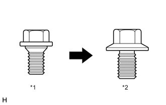
*1 Centering Bolt *2 Standard Bolt Centering bolts are used to mount the door hinge to the vehicle body and door. The door cannot be adjusted with the centering bolts on. Substitute the centering bolts for standard bolts when making adjustments.
-
A bolt without a torque specification is shown in the standard bolt chart.
PROCEDURE
-
INSPECT REAR DOOR PANEL SUB-ASSEMBLY
-
Check that the clearance measurements of areas "A" through "M" are within each standard range.
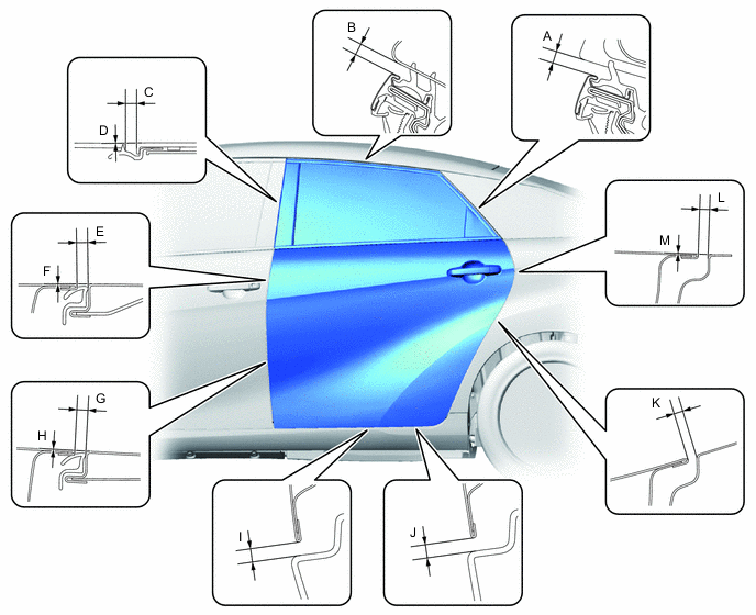
Standard Clearance Area Measurement Area Measurement A 3.5 to 6.5 mm (0.138 to 0.256 in.) B 3.5 to 6.5 mm (0.138 to 0.256 in.) C 2.8 to 5.8 mm (0.110 to 0.228 in.) D -1.5 to 1.5 mm (-0.059 to 0.059 in.) E 2.6 to 5.6 mm (0.102 to 0.220 in.) F -1.5 to 1.5 mm (-0.059 to 0.059 in.) G 2.6 to 5.6 mm (0.102 to 0.220 in.) H -1.5 to 1.5 mm (-0.059 to 0.059 in.) I 3.8 to 6.8 mm (0.150 to 0.228 in.) J 3.8 to 6.8 mm (0.150 to 0.228 in.) K 2.3 to 5.3 mm (0.091 to 0.209 in.) L 2.3 to 5.3 mm (0.091 to 0.209 in.) M -1.5 to 1.5 mm (-0.059 to 0.059 in.) - -
-
-
REMOVE REAR DOOR LOCK STRIKER COVER
-
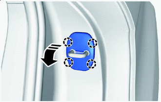

Remove in this Direction Disengage the claws to remove the rear door lock striker cover as shown in the illustration.
-
-
ADJUST REAR DOOR PANEL SUB-ASSEMBLY
-
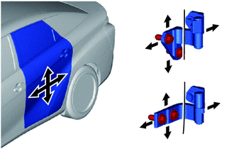
Using SST, adjust the door horizontally and vertically by loosing the 4 body side hinge bolts.
- SST
- 09812-00010
-
Tighten the 4 body side hinge bolts after the adjustment.
- Torque:
- 32.5 N*m { 331 kgf*cm, 24 ft.*lbf }
-
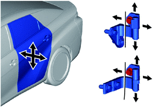
Adjust the door horizontally and vertically by loosing the 2 body side hinge bolts.
-
Tighten the 2 body side hinge bolts after the adjustment.
- Torque:
- 32.5 N*m { 331 kgf*cm, 24 ft.*lbf }
-
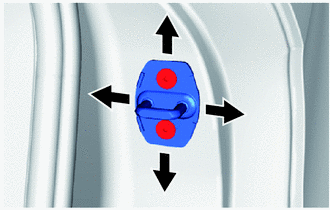
Using a T40 "TORX" socket wrench, slightly loosen the 2 striker mounting screws.
-
Using a brass bar and a hammer, hit the striker to adjust its position.
-
Using a T40 "TORX" socket wrench, tighten the 2 striker mounting screws after adjustment.
- Torque:
- 23 N*m { 235 kgf*cm, 17 ft.*lbf }
-
-
INSTALL REAR DOOR LOCK STRIKER COVER
-
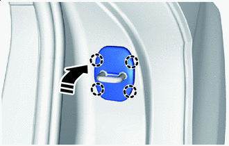
Install in this Direction Engage the claws to install the rear door lock striker cover as shown in the illustration.
-