WINDSHIELD DEICER SYSTEM TERMINALS OF ECU
-
CHECK AIR CONDITIONING AMPLIFIER ASSEMBLY
-
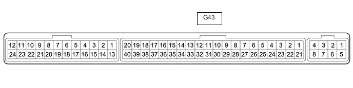
Disconnect the G43 air conditioning amplifier assembly connector.
-
Measure the voltage and resistance according to the value(s) in the table below.
Tester Connection Wiring Color Terminal Description Condition Specified Condition G43-1 (IG+) - Body ground B - Body ground Power source (IG) Power switch on (IG) 11 to 14 V Power switch off Below 1 V G43-21 (B) - Body ground GR - Body ground Auxiliary battery power supply Power switch off 11 to 14 V G43-14 (GND) - Body ground W-B - Body ground Ground Always Below 1 Ω -
Reconnect the G43 air conditioning amplifier assembly connector.
-
Measure the voltage and check the waveform according to the value(s) in the table below.
Tester Connection Wiring Color Terminal Description Condition Specified Condition G43-11 (CANH)*1 LG - - - G43-12 (CANL)*1 W - - - G43-36 (FDEF) - Body ground W - Body ground Wiper Deicer signal Power switch on (IG), windshield deicer switch off 11 to 14 V Power switch on (IG), windshield deicer switch on Below 1 V
-
*1: Refer to FAIL-SAFE CHART for CAN communication system (for LHD or for RHD).
-
-
-
CHECK INTEGRATION CONTROL AND PANEL ASSEMBLY

-
Disconnect the G49 integration control and panel assembly connector.
-
Measure the voltage and resistance according to the value(s) in the table below.
Tester Connection Wiring Color Terminal Description Condition Specified Condition G49-9 (IG+) - Body ground P - Body ground Power source (IG) Power switch on (IG) 11 to 14 V Power switch off Below 1 V G49-1 (+B) - Body ground LG - Body ground Auxiliary battery power supply Power switch off 11 to 14 V G49-16 (GND) - Body ground W-B - Body ground Ground Always Below 1 Ω -
Reconnect the G49 integration control and panel assembly connector.
-
Check the waveform according to the table below.
Tester Connection Wiring Color Terminal Description Condition Specified Condition G49-4 (CANH)*1 BR - - - G49-5 (CANL)*1 W - - -
-
*1: Refer to FAIL-SAFE CHART for CAN communication system (for LHD or for RHD).
-
-