ROOF HEADLINING INSTALLATION
PROCEDURE
-
INSTALL ROOF HEADLINING ASSEMBLY
-
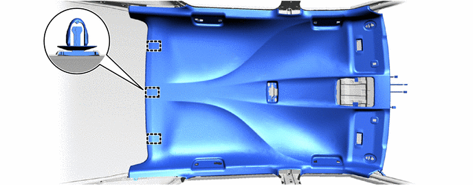
Install the 3 clips to the roof head lining assembly.
-
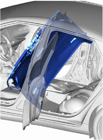
As shown in the illustration, tilt the roof headlining assembly, and while bending it slightly, put it inside the vehicle through the rear door.
Note
-
Check each corner of the roof headlining assembly to make sure there is no deformation such as folding or twisting, and check that no components have fallen off, etc.
-
Be careful not to damage or scratch the roof headlining assembly or body interior.
-
-
Engage the clips to install the roof headlining assembly.
-
Connect the 3 connectors.
-
w/ Lane Departure Alert System:
-
Connect the connector.
-
-
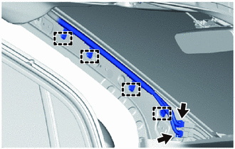
Engage the clamps.
-
Connect the 2 connectors.
-
-
INSTALL VANITY LIGHT ASSEMBLY
-
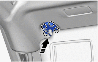
INSTALL VISOR HOLDER LH
-
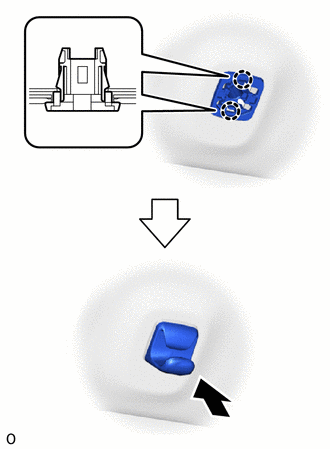
Engage the claws.
-
Install the visor holder LH as shown in the illustration.
-
-
INSTALL VISOR HOLDER RH
Tech Tips
Use the same procedure as for the LH side.
-
INSTALL VISOR ASSEMBLY LH
-
Install the visor assembly LH with the 2 screws.
-
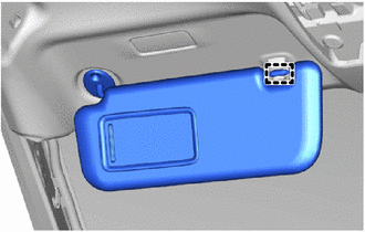
Engage the guide to connect the visor assembly LH.
-
-
INSTALL VISOR ASSEMBLY RH
Tech Tips
Use the same procedure as for the LH side.
-
INSTALL VISOR BRACKET COVER LH
-

Install in this Direction Engage the claws to install the visor bracket cover LH as shown in the illustration.
-
-
INSTALL VISOR BRACKET COVER RH
Tech Tips
Use the same procedure as for the LH side.
-
INSTALL ASSIST GRIP SUB-ASSEMBLY
Tech Tips
Using the same procedure, install every assist grip sub-assembly.
-
Install the 2 clips to the assist grip sub-assembly.
-
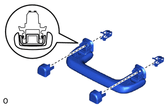
Temporarily install the 2 assist grip covers to the assist grip sub-assembly as shown in the illustration.
-
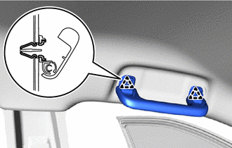
Engage the 2 clips to install the assist grip sub-assembly.
-
-
INSTALL NO. 1 ROOM LIGHT ASSEMBLY
-
INSTALL MAP LIGHT ASSEMBLY
-
INSTALL NO. 1 LANE RECOGNITION COVER (w/ Lane Departure Alert System)
-
INSTALL INNER REAR VIEW MIRROR STAY HOLDER COVER
-
INSTALL RAIN SENSOR COVER
-
INSTALL PROTECTOR
-
INSTALL ROOF SIDE INNER GARNISH ASSEMBLY LH
-
Install in this Direction Engage the guides to install the roof side inner garnish assembly LH as shown in the illustration.
-
Install in this Direction Engage the clips as shown in the illustration.
-
-
INSTALL ROOF SIDE INNER GARNISH ASSEMBLY RH
Tech Tips
Use the same procedure as for the LH side.
-
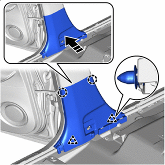
INSTALL REAR SEAT SIDE GARNISH LH
-
Install in this Direction Engage the guide and claw to install the rear seat side garnish LH as shown in the illustration.
-
-
INSTALL REAR SEAT SIDE GARNISH RH
Tech Tips
Use the same procedure as for the LH side.
-
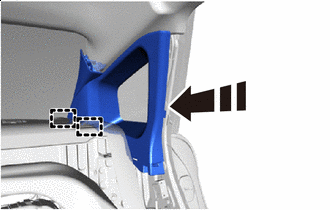
INSTALL CENTER PILLAR GARNISH ASSEMBLY LH
-
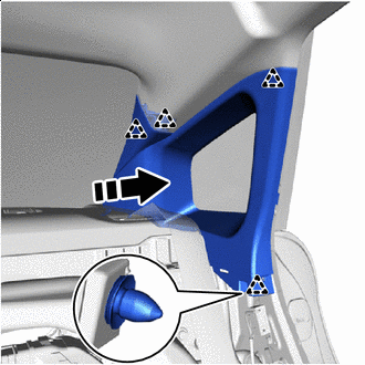
Install in this Direction Engage the clip to install the center pillar garnish assembly LH as shown in the illustration.
-
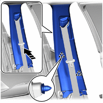
Install in this Direction Engage the clip as shown in the illustration.
-
Install the screw.
-
-
INSTALL CENTER PILLAR GARNISH ASSEMBLY RH
Tech Tips
Use the same procedure as for the LH side.
-
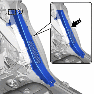
INSTALL CENTER PILLAR LOWER GARNISH LH
-
Install in this Direction Engage the claws and clips to install the center pillar lower garnish LH as shown in the illustration.
-
-
INSTALL CENTER PILLAR LOWER GARNISH RH
Tech Tips
Use the same procedure as for the LH side.
-
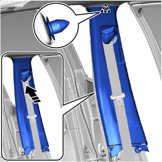
CONNECT FRONT SEAT OUTER BELT ASSEMBLY LH
-
Connect the front seat outer belt assembly LH with the bolt.
- Torque:
- 42 N*m { 428 kgf*cm, 31 ft.*lbf }
-
-
CONNECT FRONT SEAT OUTER BELT ASSEMBLY RH
Tech Tips
Use the same procedure as for the LH side.
-
INSTALL LAP BELT OUTER ANCHOR COVER
Tech Tips
Use the same procedures for the opposite side.
-
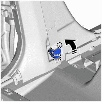
Install in this Direction Engage the guide and claws to install the lap belt outer anchor cover as shown in the illustration.
-
-
INSTALL REAR DOOR OPENING TRIM WEATHERSTRIP LH
-
INSTALL REAR DOOR OPENING TRIM WEATHERSTRIP RH
Tech Tips
Use the same procedure as for the LH side.
-
INSTALL REAR DOOR SCUFF PLATE LH
-
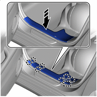
Install in this Direction Engage the guide and claws to install the rear door scuff plate LH as shown in the illustration.
-
-
INSTALL REAR DOOR SCUFF PLATE RH
Tech Tips
Use the same procedure as for the LH side.
-
INSTALL FRONT PILLAR GARNISH LH
-
INSTALL FRONT PILLAR GARNISH RH
Tech Tips
Use the same procedure as for the LH side.
-
INSTALL FRONT DOOR OPENING TRIM WEATHERSTRIP LH
-
INSTALL FRONT DOOR OPENING TRIM WEATHERSTRIP RH
Tech Tips
Use the same procedure as for the LH side.
-
INSTALL NO. 1 INSTRUMENT PANEL CUSHION
-
INSTALL NO. 1 INSTRUMENT PANEL SPEAKER PANEL SUB-ASSEMBLY
-
INSTALL NO. 2 INSTRUMENT PANEL SPEAKER PANEL SUB-ASSEMBLY
Tech Tips
Use the same procedure as for the No. 1 side.
-
INSTALL FRONT CONSOLE BOX
-
INSTALL REAR SEAT ASSEMBLY
-
INSTALL FRONT SEAT ASSEMBLY LH
-
INSTALL FRONT SEAT ASSEMBLY RH
Tech Tips
Use the same procedure as for the LH side.