INSTRUMENT PANEL SAFETY PAD INSTALLATION
CAUTION / NOTICE / HINT
Tech Tips
-
Use the same procedure for RHD and LHD vehicles.
-
The procedure listed below is for LHD vehicles.
PROCEDURE
-
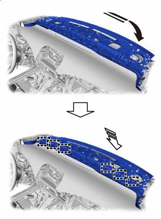
INSTALL UPPER INSTRUMENT PANEL SUB-ASSEMBLY
-
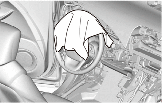
*a Cloth To prevent scratches or damage to the interior during installation, place cloth in the location shown in the illustration.
-
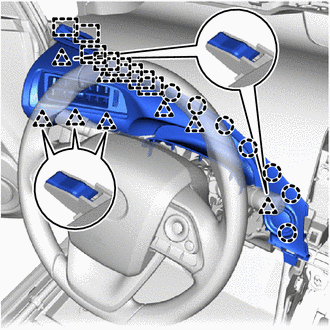
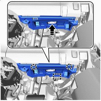
Install the upper instrument panel sub-assembly:
-
Install the upper instrument panel sub-assembly as shown in the illustration.
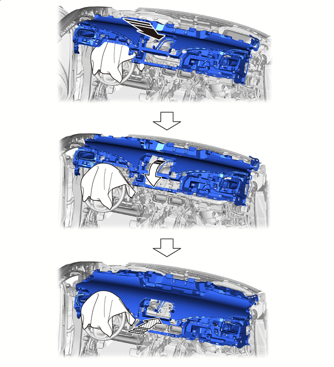

Install in this Direction (1) 
Install in this Direction (2) 
Install in this Direction (3) - -
-
-
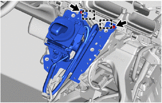
Engage the guides to install the shift lever with bracket.
-
Install the 2 screws <H>.
-
Install the 4 bolts <D>.
-
Engage the guide to connect the No. 3 antenna cord sub-assembly.
-
Install the bolt.
-
Connect the connectors and engage the clamps.
-
Connect the instrument panel wire.
-
Install the 10 bolts <C> and nut <A>.
-
Install the 2 bolts <D>.
- Torque:
- 20 N*m { 204 kgf*cm, 15 ft.*lbf }
-
-
INSTALL COMBINATION METER ASSEMBLY
-
INSTALL LOWER INSTRUMENT PANEL ASSEMBLY
-
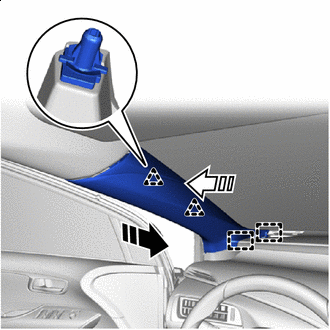
Install in this Direction (1) Install in this Direction (2) Push in the direction shown by the arrow (1) in the illustration and temporarily install the lower instrument panel assembly.
-
Push in the direction indicated by the arrow (2) in the illustration and engage the guides to install the lower instrument panel assembly.
-
Connect the connector.
-
Install the 2 bolts <B> and 10 screws <G>.
-
Install the 2 clips.
-
-
INSTALL REAR CONSOLE BOX SUB-ASSEMBLY
-
INSTALL NO. 4 CONSOLE BOX DUCT
-
INSTALL CONSOLE REAR END PANEL SUB-ASSEMBLY
-
INSTALL NO. 1 CONSOLE BOX DUCT
-
INSTALL NO. 2 CONSOLE BOX DUCT
-
INSTALL FRONT NO. 1 CONSOLE BOX INSERT
-
INSTALL FRONT NO. 2 CONSOLE BOX INSERT
Tech Tips
Use the same procedure as for the No. 1 side.
-
INSTALL NO. 6 CONSOLE BOX RETAINER
-
INSTALL MOBILE WIRELESS CHARGER CRADLE ASSEMBLY
-
INSTALL STEREO JACK ADAPTER ASSEMBLY
-
INSTALL CONSOLE COMPARTMENT BOX ASSEMBLY
-
INSTALL FRONT CONSOLE BOX COVER
-
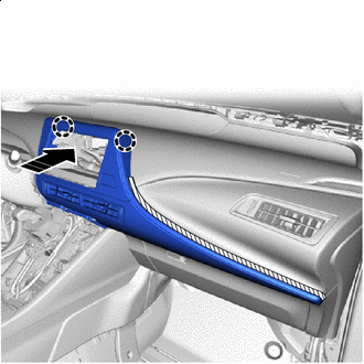
INSTALL GLOVE COMPARTMENT DOOR ASSEMBLY
-
Connect the connector.
-
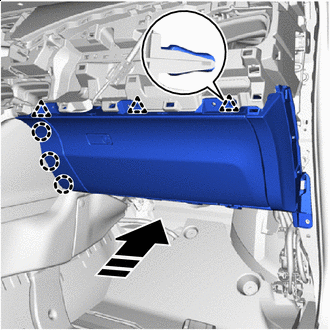
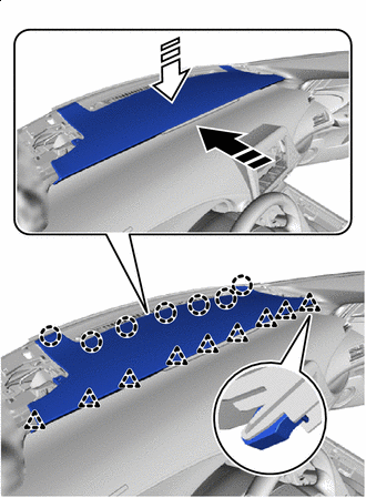
Install in this Direction Engage the claws and clips to install the glove compartment door assembly as shown in the illustration.
-
Install the 2 bolts <C> and 3 screws <H>.
-
-
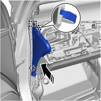
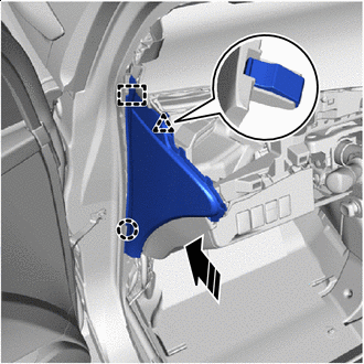
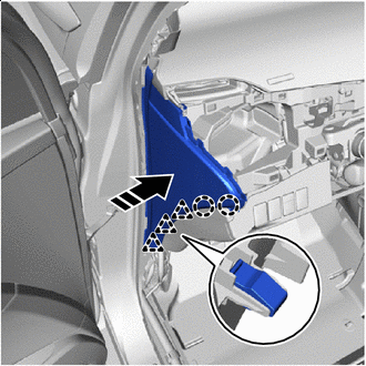
INSTALL INSTRUMENT SIDE PANEL RH (for LHD)
-
Connect the connector.
-
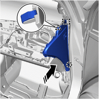
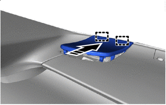
Install in this Direction Engage the guide, claw and clip as shown in the illustration.
-
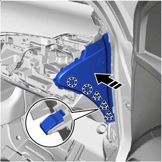
Install in this Direction Engage the claws and clips to install the instrument side panel RH as shown in the illustration.
-
-
INSTALL INSTRUMENT SIDE PANEL LH (for RHD)
-
Connect the connector.
-
Install in this Direction Engage the guide, claw and clip as shown in the illustration.
-
Install in this Direction Engage the claws and clips to install the instrument side panel LH as shown in the illustration.
-
-
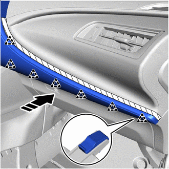
INSTALL NO. 2 INSTRUMENT PANEL REGISTER ASSEMBLY
Install in this Direction
-
Engage the clips and claws to install the No. 2 instrument panel register assembly as shown in the illustration.
-
-
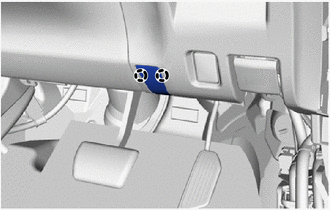
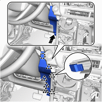
INSTALL INSTRUMENT PANEL LOWER FINISH PANEL
-
for LHD:
-
Connect the connectors and engage the clamp.
-
Install in this Direction Engage the claws and clips to install the instrument panel lower finish panel as shown in the illustration.
-
Install the bolt <C>.
-
-
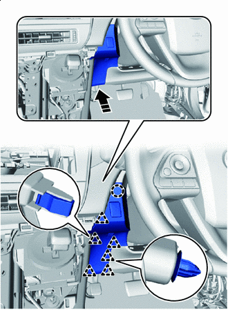
for RHD:
-
Connect the connectors and engage the clamp.
-
Install in this Direction Engage the claws and clips to install the instrument panel lower finish panel as shown in the illustration.
-
Install the screw <I> and bolt <C>.
-
Engage the claws to close the cover.
-
-
-
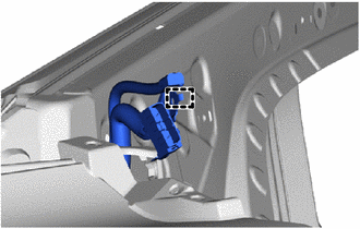
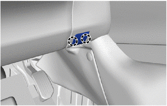
CONNECT HOOD LOCK CONTROL LEVER SUB-ASSEMBLY
-
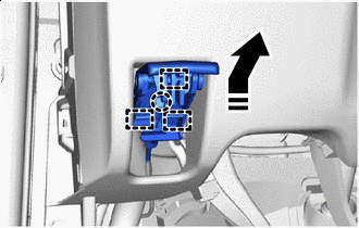
Install in this Direction Engage the guides and claw to connect the hood lock control lever sub-assembly as shown in the illustration.
-
-
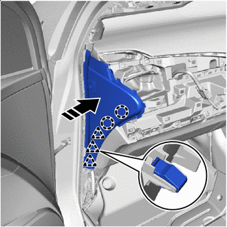
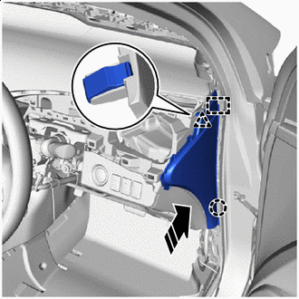
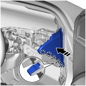
INSTALL INSTRUMENT SIDE PANEL LH (for LHD)
-
Install in this Direction Engage the guide, claw and clip as shown in the illustration.
-
Install in this Direction Engage the claws and clips to install the instrument side panel LH as shown in the illustration.
-
-
INSTALL INSTRUMENT SIDE PANEL RH (for RHD)
-
Install in this Direction Engage the guide, claw and clip as shown in the illustration.
-
Install in this Direction Engage the claws and clips to install the instrument side panel RH as shown in the illustration.
-
-
INSTALL NO. 1 INSTRUMENT PANEL REGISTER ASSEMBLY
-
for LHD:
-
Connect the connector.
-
-
Engage the guides, claws and clips to install the No. 1 instrument panel register assembly.
-
-
INSTALL UPPER STEERING COLUMN COVER
-
INSTALL LOWER STEERING COLUMN COVER
-
INSTALL RADIO RECEIVER ASSEMBLY
-
INSTALL INSTRUMENT CENTER PANEL REGISTER ASSEMBLY
-
Connect the connector.
-
Install in this Direction Engage the claws as shown in the illustration.
Note
The claws in the illustration are 2-stage, so in this step, engage the tips.
-
Install in this Direction Engage the clips and claws as shown in the illustration.
-
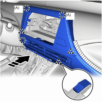
Install in this Direction Engage the claws and clips to install the instrument center panel register assembly as shown in the illustration.
Note
The claws (A) in the illustration are 2-stage, so in this step, engage the end portions.
-
Remove the protective tape.
-
Close the glove compartment door assembly.
-
-
INSTALL INSTRUMENT CENTER UPPER CLUSTER FINISH PANEL
-
Install in this Direction for LHD:
-
Engage the claw and clips to install the instrument center upper cluster finish panel as shown in the illustration.
-
Install the screw <H> or <I>.
-
Engage the claws to close the cover.
-
-
for RHD:
-
Connect the connector and engage the clamp.
-
Install in this Direction Engage the claw and clips to install the instrument center upper cluster finish panel as shown in the illustration.
-
-
-
INSTALL INTEGRATION CONTROL AND PANEL ASSEMBLY
-
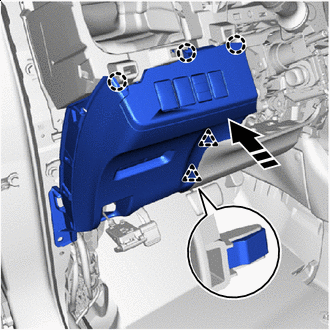
INSTALL NO. 1 INSTRUMENT PANEL UNDER COVER SUB-ASSEMBLY
-
for LHD:
-
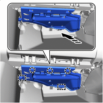
Connect the connectors and engage the clamp.
-
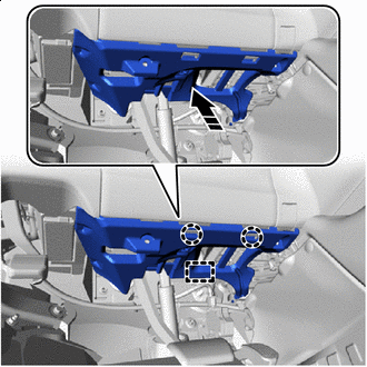
Install in this Direction Engage the guide and claws to install the No. 1 instrument panel under cover sub-assembly as shown in the illustration.
-
Install the 2 screws <H> or <I>.
-
-
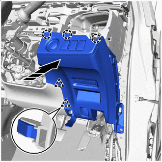
for RHD:
-
Connect the connectors and engage the clamp.
-
Install in this Direction Engage the guide and claws to install the No. 1 instrument panel under cover sub-assembly as shown in the illustration.
-
Install the 2 screws <H> or <I>.
-
-
-
INSTALL FRONT PILLAR GARNISH LH
-
Remove the protective cover.
-
Install 2 new front pillar garnish clips to the front pillar garnish RH.
-
Install in this Direction (1) Install in this Direction (2) Engage the guides and clips to install the front pillar garnish LH as shown in the illustration.
-
-
INSTALL FRONT PILLAR GARNISH RH
Tech Tips
Use the same procedure as for the LH side.
-
CONNECT FRONT DOOR OPENING TRIM WEATHERSTRIP LH
-
Connect the front door opening trim weatherstrip LH.
-
-
CONNECT FRONT DOOR OPENING TRIM WEATHERSTRIP RH
Tech Tips
Use the same procedure as for the LH side.
-
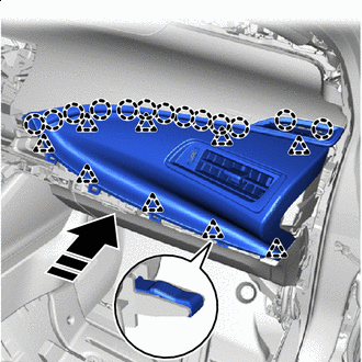
INSTALL NO. 1 INSTRUMENT PANEL CUSHION
-
Install in this Direction (1) Install in this Direction (2) Engage the claws and clips to install the No.1 instrument panel cushion as shown in the illustration.
-
Install the 5 clips.
-
Install the 2 screws <H>.
-
-
INSTALL FRONT NO. 2 SPEAKER ASSEMBLY
-
INSTALL NO. 1 INSTRUMENT PANEL SPEAKER PANEL SUB-ASSEMBLY
-
Install in this Direction Engage the guides as shown in the illustration.
-
Install in this Direction Engage the claws and clips to install the No. 1 instrument panel speaker panel sub-assembly as shown in the illustration.
-
-
INSTALL NO. 2 INSTRUMENT PANEL SPEAKER PANEL SUB-ASSEMBLY
Tech Tips
Use the same procedure as for the No. 1 side.
-
INSTALL COWL SIDE TRIM BOARD LH
-
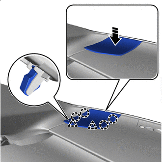
Install in this Direction Engage the clip to install the cowl side trim board LH as shown in the illustration.
-
Install the clip.
-
-
INSTALL COWL SIDE TRIM BOARD RH
Tech Tips
Use the same procedure as for the LH side.
-
INSTALL NO. 2 INSTRUMENT PANEL UNDER COVER SUB-ASSEMBLY
-
for LHD:
-
Connect the connector and engage the clamp.
-
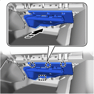
Install in this Direction Engage the guide and claws to install the No. 2 instrument panel under cover sub-assembly as shown in the illustration.
-
-
for RHD:
-
Connect the connector and engage the clamp.
-
Install in this Direction Engage the guides and claws to install the No. 2 instrument panel under cover sub-assembly as shown in the illustration.
-
-
-
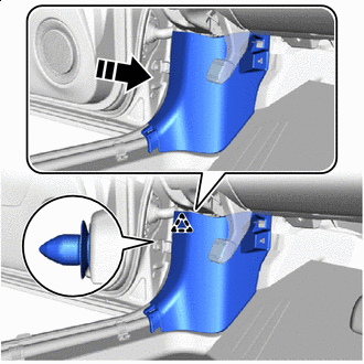
INSTALL FRONT DOOR SCUFF PLATE LH (for LHD)
-
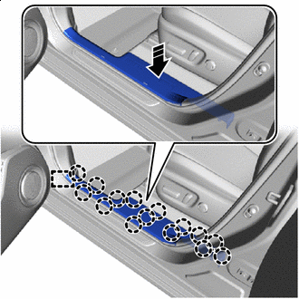
Install in this Direction Engage the guide and claws to install the front door scuff plate LH as shown in the illustration.
-
-
INSTALL FRONT DOOR SCUFF PLATE RH (for RHD)
-
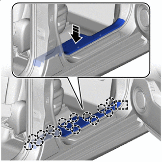
Install in this Direction Engage the guide and claws to install the front door scuff plate RH as shown in the illustration.
-
-
INSTALL FRONT SEAT ASSEMBLY RH (for LHD)
-
INSTALL FRONT SEAT ASSEMBLY LH (for RHD)
-
CUSTOMIZE POWER TILT AND POWER TELESCOPIC STEERING COLUMN