HEATER ASSEMBLY REMOVAL
CAUTION / NOTICE / HINT
CAUTION:
-
This vehicle has contains high voltage circuits standardized with orange colored wiring and connectors, so follow the instructions in this manual to perform the procedures correctly.
-
If the correct procedures are not followed according to the instructions in this manual, there is a danger of electric shock from the high voltage circuits.
-

Be sure to wear insulating gloves when working on high voltage wiring or components.
-
If work is performed without wearing insulating gloves, there is a danger of electric shock.
PROCEDURE
-
CAUTION
Note
-
The coolant (Toyota genuine FC stack coolant) is an exclusive coolant.
-
The coolant (Toyota genuine FC stack coolant) cannot be reused, so when filling, be sure to fill with new coolant (Toyota genuine FC stack coolant).
-
To prevent degradation of coolant (Toyota genuine FC stack coolant) performance, do not add or fill any other substances such as tap water or battery electrolyte refill liquid.
-
Do not use cotton work gloves or other gloves that could shed fibers.
-
DO NOT use any container that has previously been used to fill substances such as oil.
-
To prevent foreign matter from contaminating the coolant (Toyota genuine FC stack coolant) passages, wash out the prepared container with tap water, then wipe away any water remaining inside the container before using it.
-
If the coolant (Toyota genuine FC stack coolant) passages are filled incorrectly, follow the countermeasures according to "Countermeasures when coolant (Toyota genuine FC stack coolant) passages are filled incorrectly".
-
When the vehicle is parked with the power switch off, if the FC control ECU judges that the FC stack temperature will go below 0°C, it activates the FC air compressor, hydrogen pump and FC cooling water pump for a maximum of 180 seconds and drains water from the FC stack assembly. When performing inspection or repairs with the power switch off (not On or Ready), disconnect the cable from the negative auxiliarybattery terminal before performing work.
-
-
REMOVE FRONT BUMPER LOWER ABSORBER
-
REMOVE NO. 2 MOTOR UNDER COVER
-
REMOVE FRONT FLOOR COVER LH
-
REMOVE FRONT FLOOR COVER RH
-
REMOVE SUSPENSION MEMBER TO FRONT CROSSMEMBER BRACE SUB-ASSEMBLY
-
DRAIN FC STACK COOLANT
-
REMOVE SERVICE PLUG GRIP (for EV)
-
REMOVE FC STACK SERVICE PLUG GRIP
-
REMOVE INVERTER COVER
-
REMOVE INVERTER TERMINAL COVER
-
CHECK TERMINAL VOLTAGE
-
INSTALL INVERTER TERMINAL COVER
-
REMOVE FC INVERTER INPUT JUNCTION ASSEMBLY
-
REMOVE FC COOLING WATER TEMPERATURE CONTROL VALVE
-
REMOVE ELECTRIC HEATER SUB-ASSEMBLY
-
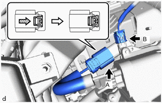
As shown in the illustration, release the green lock of connector A and disconnect the connector.
CAUTION:
Make sure to wear insulating gloves.
Note
Insulate the disconnected terminals and connector with insulating tape.
-
Disconnect connector B.
-
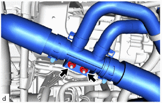
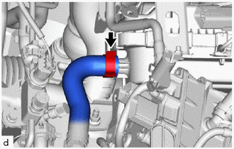
Remove the 2 nuts to disconnect the water hose.
-
Remove the 2 bolts to disconnect the FC cooling water valve inlet pipe.
-
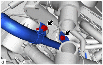
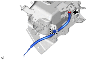
As shown in the illustration, release the green lock of connector and disconnect the connector.
CAUTION:
Make sure to wear insulating gloves.
Note
Insulate the disconnected terminals and connector with insulating tape.
-
Disengage the clamps to separate the auxiliary inverter harness.
-
Remove the bolt.
-
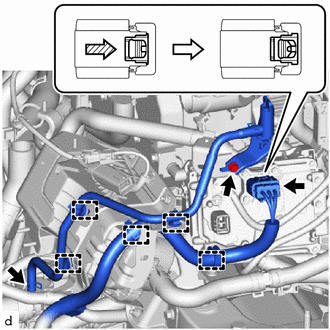
Slide the hose clip to disconnect the FC water pump drain hose assembly.
-
Disengage the clamps to remove the FC water pump drain hose assembly.
-
Slide the hose clip to disconnect the water hose sub-assembly.
Note
-
To prevent contamination by foreign matter or water droplets, protect the connecting portions of the water hose sub-assembly and electric heater sub-assembly with plastic bags, etc.
-
Do not apply excessive force to water hose sub-assembly.
-
Prepare a drain pan or cloth in case the coolant leaks.
-
-
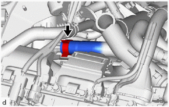
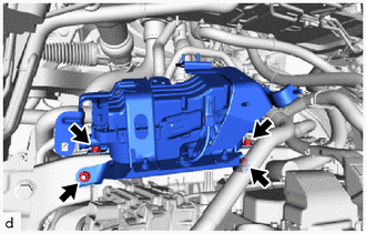
Remove the 2 bolts and 2 nuts, and electric heater sub-assembly.
Note
Prepare a drain pan or cloth in case the coolant leaks.
-
Remove the nut.
-
Disengage the clamp to remove the ground wire .
-