HEATER ASSEMBLY INSTALLATION
PROCEDURE
-
INSTALL ELECTRIC HEATER SUB-ASSEMBLY
-
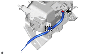
Engage the clamp.
-
Install the ground wire with the nut.
- Torque:
- 5.5 N*m { 56 kgf*cm, 49 in.*lbf }
-
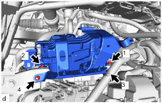
Temporarily install the electric heater sub-assembly with the 2 bolts and 2 nuts.
-
Tighten the 2 bolts and 2 nuts in the order shown in the illustration.
- Torque:
- 9.8 N*m { 100 kgf*cm, 87 in.*lbf }
-
Install the ground wire with the bolt.
- Torque:
- 8.4 N*m { 86 kgf*cm, 74 in.*lbf }
-
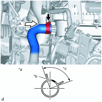
*a View A *b Marking (yellow) *c Clip Installation Angle (90°) Align the marking (yellow) with the space between the ribs of the electric heater sub-assembly, connect the water hose sub-assembly and install the hose clips to the area shown in the illustration.
Note
Do not apply excessive force to water hose sub-assembly.
-
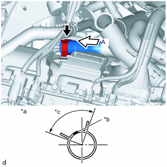
*a View A *b Marking (white) *c Clip Installation Angle (90°) Align the marking (white) with the space between the ribs of the electric heater sub-assembly, connect the water hose sub-assembly and install the hose clips to the area shown in the illustration.
Note
Do not apply excessive force to water hose sub-assembly.
-
Engage the clamps.
-
Connect the FC water pump drain hose assembly and install the hose clips.
-
Install the bolt.
-
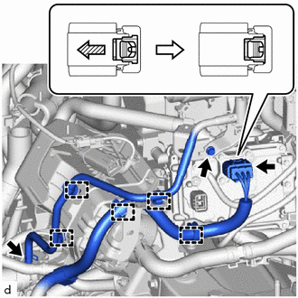
Remove the protective tape wrapped around connector, and as shown in the illustration, connect connector and lower the green lock to lock it securely.
CAUTION:
Make sure to wear insulating gloves.
Note
Make sure that the connector is connected securely.
-
Connect the FC cooling water valve inlet pipe and install the 2 bolts.
- Torque:
- 8.0 N*m { 82 kgf*cm, 71 in.*lbf }
-
Remove the 2 nuts to disconnect the water hose.
- Torque:
- 8.0 N*m { 82 kgf*cm, 71 in.*lbf }
-
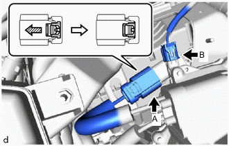
Connect connector B.
-
Remove the protective tape wrapped around connector A, and as shown in the illustration, connect connector A and lower the green lock to lock it securely.
CAUTION:
Make sure to wear insulating gloves.
Note
Make sure that the connector is connected securely.
-
-
INSTALL FC COOLING WATER TEMPERATURE CONTROL VALVE
-
INSTALL FC INVERTER INPUT JUNCTION ASSEMBLY
-
INSTALL INVERTER COVER
-
INSTALL FC STACK SERVICE PLUG GRIP
-
INSTALL SERVICE PLUG GRIP (for EV)
-
ADD FC STACK COOLANT
-
INSPECT FC STACK COOLANT LEAKS
-
INSTALL SUSPENSION MEMBER TO FRONT CROSSMEMBER BRACE SUB-ASSEMBLY
-
INSTALL FRONT FLOOR COVER RH
-
INSTALL FRONT FLOOR COVER LH
-
INSTALL NO. 2 MOTOR UNDER COVER
-
INSTALL FRONT BUMPER ABSORBER LOWER