SOLAR SENSOR INSPECTION
PROCEDURE
-
INSPECT SOLAR SENSOR
-
Disconnect the automatic light control sensor (solar sensor).
-
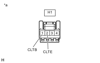
*a Front view of wire harness connector
(automatic light control sensor (solar sensor))
Check the voltage
Measure the voltage and resistance according to the value(s) in the table below.
Standard Voltage Tester Connection Switch Condition Specified Condition H1-1(CLTB) - H1-2(CLTE) IG ON 11 to 14 V Tech Tips
If the specified condition is not met, replace the vehicle wire harness.
-
Check the resistance
Measure the resistance according to the value(s) in the table below.
Standard Resistance Tester Connection Switch Condition Specified Condition H1-2(CLTE) - Body ground Always Below 1 Ω Tech Tips
If the specified condition is not met, replace the vehicle wire harness.
-
Connect the automatic light control sensor (solar sensor).
-
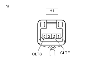
*a Component with harness connected
(automatic light control sensor(solar sensor))
Check the waveform
Use the oscilloscope and check the waveform in the terminal spaces.
Note
With the connector connected as is, check from the rear side of the connector.
Standard Tester Connection Switch Condition Standard H1-4(CLTS) - H1-2(CLTE) IG on (IG), light control switch in AUTO position Correct waveform is as shown Tech Tips
If the specified condition is not met, replace the solar sensor.
-
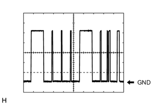
Waveform
Item Content Terminal H1-4(CLTS) - H1-2(CLTE) Equipment Setting 2V/DIV.,10ms/DIV. Condition IG on (IG), head light dim switch in AUTO position Tech Tips
The communication waveform changes according to the surrounding brightness.
-
-