FRONT EVAPORATOR TEMPERATURE SENSOR INSTALLATION
PROCEDURE
-
INSTALL NO. 1 COOLER THERMISTOR
-
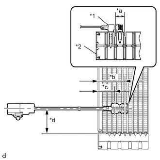
*1 Resin Case *2 No. 1 cooler evaporator sub-assembly *a Range A *b 34.3 mm (1.35 in.) (from end face of No. 1 cooler evaporator sub-assembly) *c 20.9 mm (0.823 in.) (from end face of No. 1 cooler evaporator sub-assembly) *d 50.0 mm (1.97 in.) (from tank upper surface) Install the No. 1 cooler thermistor as shown in the illustration.
Note
-
To ensure sufficient holding power for the No. 1 cooler thermistor, it may only be inserted once.
-
When reusing the No. 1 cooler evaporator, insert the cooler thermistor in the next row to the left or right of the row that the thermistor was in before, and the insertion position should also be offset (area A).
-
After inserting the thermistor, do not apply excessive force to the wire.
-
Insert it straight in until the edge of the resin case contacts the edge of the No. 1 cooler evaporator.
-
-
-
INSTALL NO. 1 COOLER EVAPORATOR SUB-ASSEMBLY
-
INSTALL COOLER EXPANSION VALVE
-
INSTALL AIR CONDITIONING RADIATOR ASSEMBLY