CONDENSER INSTALLATION
PROCEDURE
-
INSTALL COOLER CONDENSER ASSEMBLY
-
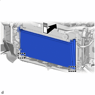

Install in this Direction In the direction shown by the arrows in the illustration, engage the guides and temporarily install the cooler condenser assembly.
Note
Do not damage the cooler condenser assembly or radiator assembly when installing the cooler condenser assembly.
-
Install the cooler condenser assembly with the 4 bolts.
- Torque:
- 7.0 N*m { 71 kgf*cm, 62 in.*lbf }
-
-
CONNECT AIRCONDITIONER TUBE AND ACCESSORY ASSEMBLY
-
Remove the vinyl tape from the airconditioner tube and accessory assembly and cooler condenser assembly.
-
Apply sufficiently compressor oil to a new O-ring and fitting surface of the airconditioner tube and accessory assembly.
Compressor Oil ND-OIL 12 or equivalent -
Install the O-ring to the airconditioner tube and accessory assembly.
Note
Keep the O-rings and O-ring fitting surfaces free of foreign matter.
-
Connect the airconditioner tube and accessory assembly to the cooler condenser assembly with the bolt.
- Torque:
- 5.4 N*m { 55 kgf*cm, 48 in.*lbf }
-
-
CONNECT DISCHARGE TUBE SUB-ASSEMBLY
-
Remove the vinyl tape from the discharge tube sub-assembly and cooler condenser assembly.
-
Apply sufficiently compressor oil to a new O-ring and fitting surface of the discharge tube sub-assembly.
Compressor Oil ND-OIL 12 or equivalent -
Install the O-ring to the discharge tube sub-assembly.
Note
Keep the O-rings and O-ring fitting surfaces free of foreign matter.
-
Connect the discharge tube sub-assembly to the cooler condenser assembly with the bolt.
- Torque:
- 5.4 N*m { 55 kgf*cm, 48 in.*lbf }
-
-
INSTALL COOL AIR INTAKE DUCT RETAINER SUB-ASSEMBLY
-
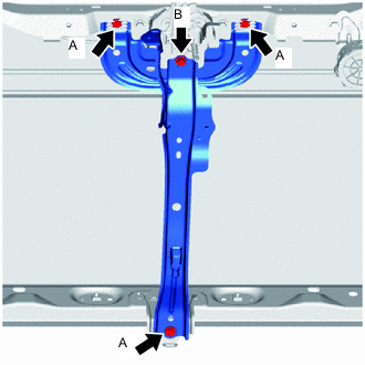
Temporarily install the cool air intake duct retainer sub-assembly with the 4 bolts.
-
Tighten the 3 bolts A.
- Torque:
- 12.5 N*m { 127 kgf*cm, 9 ft.*lbf }
-
Tighten the bolt B.
- Torque:
- 8.0 N*m { 82 kgf*cm, 71 in.*lbf }
-
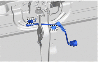
Engage the clamps to install the front door courtesy lamp switch assembly harness.
-
Connect the vehicle approaching speaker assembly connector.
-
Connect the thermistor assembly connector.
-
-
INSTALL LOW PITCHED HORN ASSEMBLY
-
INSTALL HIGH PITCHED HORN ASSEMBLY
-
INSTALL MILLIMETER WAVE RADAR SENSOR ASSEMBLY
-
INSTALL NO. 1 RADIATOR AIR GUIDE LH
-
INSTALL NO. 1 RADIATOR AIR GUIDE RH
-
INSTALL FRONT BUMPER REINFORCEMENT SUB-ASSEMBLY
-
INSTALL FRONT BUMPER ENERGY ABSORBER
-
INSTALL HEADLIGHT ASSEMBLY LH
-
INSTALL HEADLIGHT ASSEMBLY RH
Tech Tips
Use the same procedure for the RH side and LH side.
-
CHARGE AIR CONDITIONING SYSTEM WITH REFRIGERANT
-
WARM UP COMPRESSOR
-
INSPECT FOR REFRIGERANT LEAK
-
ADJUST MILLIMETER WAVE RADAR SENSOR ASSEMBLY