CONDENSER REMOVAL
CAUTION / NOTICE / HINT
For a list of calibration, initialization, and registration procedures that must be performed after removal/installation or replacement of the cooler condenser assembly, refer to the following.
| Replacement Part or Procedure | Necessary Procedures | Effects/Inoperative when not Performed | Link |
|---|---|---|---|
| Removal/installation of millimeter wave radar sensor assembly | Adjust millimeter wave radar sensor assembly | Dynamic radar cruise control system Pre-crash safety system |
PROCEDURE
-
DRAIN RECOVER REFRIGERANT FROM REFRIGERATION SYSTEM
-
REMOVE HEADLIGHT ASSEMBLY LH
-
REMOVE HEADLIGHTASSEMBLY RH
Tech Tips
Use the same procedure for the RH side and LH side.
-
REMOVE FRONT BUMPER ENERGY ABSORBER
-
REMOVE FRONT BUMPER REINFORCEMENT SUB-ASSEMBLY
-
REMOVE NO. 1 RADIATOR AIR GUIDE RH
-
REMOVE NO. 1 RADIATOR AIR GUIDE LH
-
REMOVE MILLIMETER WAVE RADAR SENSOR ASSEMBLY
-
REMOVE HIGH PITCHED HORN ASSEMBLY
-
REMOVE LOW PITCHED HORN ASSEMBLY
-
REMOVE COOL AIR INTAKE DUCT RETAINER SUB-ASSEMBLY
-
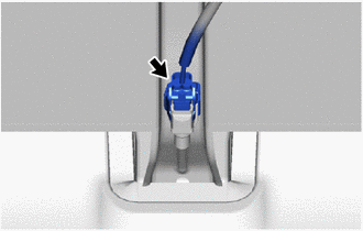
Disconnect the thermistor assembly connector.
-
Disconnect the vehicle approaching speaker assembly connector.
-
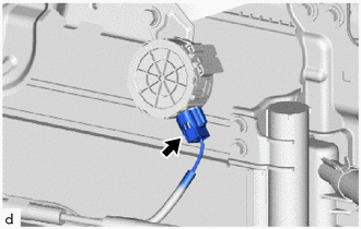
Disengage the clamps to separate the front door courtesylamp switch assembly harness.
-
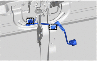
Remove the 4 bolts and cool air intake duct retainer sub-assembly.
-
-
DISCONNECT DISCHARGE TUBE SUB-ASSEMBLY
-
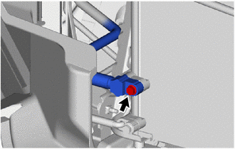
Remove the bolt to disconnect the discharge tube sub-assembly.
-
Remove the O-ring from the discharge tube sub-assembly.
Note
Wrap protective tape around the connecting portions of the disconnected discharge tube sub-assembly and the cooler condenser assembly to prevent contamination by foreign matter or water droplets.
-
-
DISCONNECT AIRCONDITIONER TUBE AND ACCESSORY ASSEMBLY
-
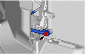
Remove the bolt to disconnect the airconditioner tube and accessory assembly.
-
Remove the O-ring from the airconditioner tube and accessory assembly.
Note
Wrap protective tape around the connecting portions of the disconnected airconditioner tube and accessory assembly and the cooler condenser assembly to prevent contamination by foreign matter or water droplets.
-
-
REMOVE COOLER CONDENSER ASSEMBLY
-
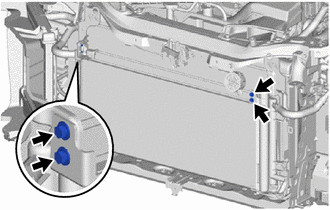
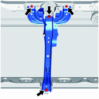
Remove the 4 bolts.
-
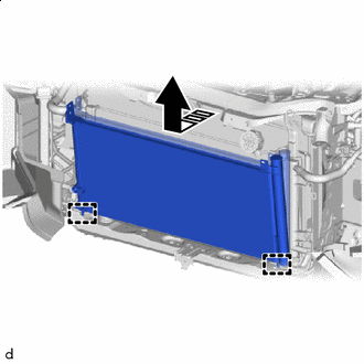

Remove in this Direction Pull up in the direction shown by the arrows in the illustration to disengage the guide, and remove the cooler condenser assembly.
Note
When removing, make sure not to damage the cooler condenser assembly or radiator assembly.
-