AIR CONDITIONING UNIT INSTALLATION
PROCEDURE
-
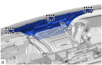
INSTALL NO. 1 AIR DUCT SUB-ASSEMBLY
-
Engage the claws to install the No. 1 air duct sub-assembly.
Note
-
If the No. 1 air duct sub-assembly is reused, it may fall off or abnormal noise may occur. Therefore, make sure to replace with a new one.
-
-
-
INSTALL NO. 2 AIR DUCT SUB-ASSEMBLY
-
Engage the claws to install the No. 2 air duct sub-assembly.
Note
-
If the No. 2 air duct sub-assembly is reused, it may fall off or abnormal noise may occur. Therefore, make sure to replace with a new one.
-
-
-
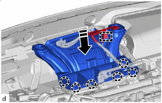
TEMPORARILY TIGHTEN AIR CONDITIONER UNIT ASSEMBLY
Note
-
As there is possibility that the air conditioner unit assembly installation bracket, be sure to hold on to the air conditioner unit assembly.
-
To protect against static electricity, do not touch the terminals of the wire harness connector installed to the air conditioner unit assembly.
-
Temporarily install the air conditioning unit assembly with bolt and nut.
-
-
INSTALL NO. 4 HEATER TO REGISTER DUCT
-
Install the No. 4 heater to register duct with the 2clips.
-
-
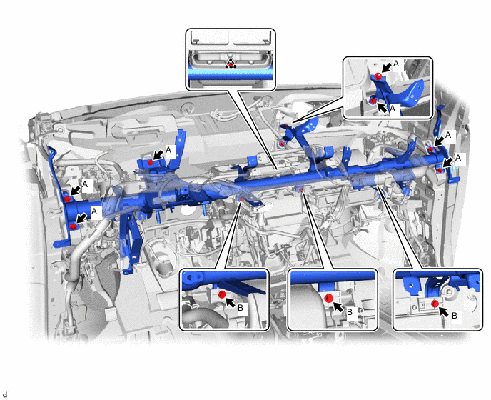
INSTALL INSTRUMENT PANEL REINFORCEMENT ASSEMBLY
-
Install the instrument panel reinforcement assembly with the 6 bolts A and clip.
-
Temporarily install the air conditioner unit assembly to the instrument panel reinforcement assembly with the 3 bolts B.
-
Engage the clamps to install the instrument wire.
-
Install the ground wire with the 3 bolts A.
- Torque:
- 8.4 N*m { 86 kgf*cm, 74 in.*lbf }
-
Install the instrument panel wire with the 2 bolts B.
- Torque:
- 12.5 N*m { 127 kgf*cm, 9 ft.*lbf }
-
Connect the 4 connectors.
-
-
INSTALL ECU INTEGRATION BOX RH
-
INSTALL INSTRUMENT PANEL JUNCTION BLOCK ASSEMBLY
-
INSTALL ECU INTEGRATION BOX LH
-
INSTALL NO. 3 AIR DUCT SUB-ASSEMBLY
-
Install the No. 3 air duct sub-assembly with the 2 nuts.
-
-
INSTALL DEFROSTER NOZZLE ASSEMBLY
-
Engage the guides to install the defroster nozzle assembly.
-
-
INSTALL LOWER DEFROSTER NOZZLE ASSEMBLY
-

Install in this Direction Engage the claws to install the lower defroster nozzle assembly as shown in the illustration.
-
-
INSTALL NO. 2 HEATER TO REGISTER DUCT
-
Install the No. 2 heater to register duct with the 7 clips.
-
Engage the clamps.
-
-
INSTALL NO. 2 INSTRUMENT PANEL BRACE SUB-ASSEMBLY
-
Install the No. 2 instrument panel brace sub-assembly with the 3 nuts and screw.
Tech Tips
Temporarily tighten the screw.
-
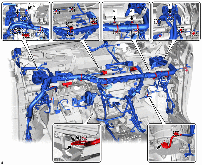
Engage the clamps to install the wire harness.
-
Install the ground wire with the bolt.
- Torque:
- 8.4 N*m { 86 kgf*cm, 74 in.*lbf }
-
-
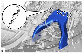
INSTALL NO. 1 INSTRUMENT PANEL BRACE SUB-ASSEMBLY
-
Install the No. 1 instrument panel brace sub-assembly with the 3 nuts and screw.
Tech Tips
Temporarily tighten the screw.
-
Engage the clamps to install the wire harness.
-
-
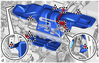
FULLY TIGHTEN AIR CONDITIONER UNIT ASSEMBLY
-
In the order shown in the illustration, fully tighten the 4 bolts, 2 screws and nut.
- Torque:
- bolt
- 9.8 N*m { 100 kgf*cm, 87 in.*lbf }
-
-
INSTALL WINDSHIELD WIPER RELAY ASSEMBLY
-
INSTALL CENTER LOWER CLUSTER SUPPORT BRACKET
-
Install the center lower cluster support bracket with the 4 bolts.
-
-
INSTALL TRANSMISSION INSTRUMENT PANEL SHIFT ASSEMBLY
-
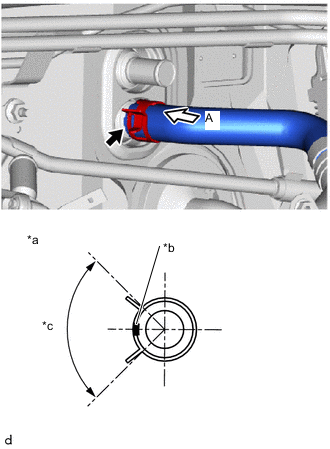
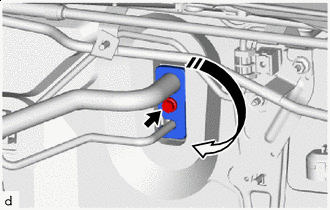
INSTALL DRAIN COOLER HOSE
-
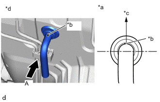
*a View A *b Marking (White) *c Top of Vehicle *d Motor Room Side As shown in the illustration, install the drain cooler hose.
Note
-
Install the drain cooler hose with its marking facing upwards.
-
Install the drain cooler hose so that it is not twisted.
-
-
-
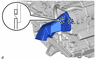
INSTALL REAR NO. 1 AIR DUCT
-
Engage the claws to install the rear No. 1 air duct.
-
-
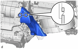
INSTALL REAR NO. 4 AIR DUCT
-
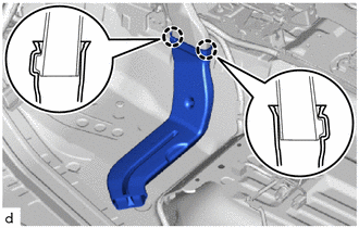
Engage the claws to install the rear No. 4 air duct.
-
-
INSTALL REAR NO. 2 AIR DUCT
Tech Tips
Use the same procedure for the RH side and LH side.
-
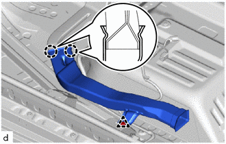
INSTALL REAR NO. 3 AIR DUCT
-
Engage the claws and install the rear No. 3 air duct.
-
Install the clip.
-
-
INSTALL REAR NO. 5 AIR DUCT
-
Engage the claws to install the rear No. 5 air duct.
-
Install the clip.
-
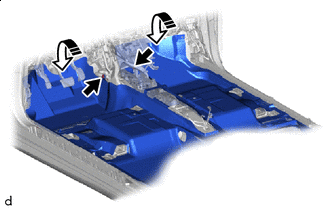
Install in this Direction Fit each fastener and install the floor carpet assembly.
-
Install the 2 clips.
-
-
INSTALL COOLER BLOWER ASSEMBLY
-
INSTALL POWER STEERING ECU ASSEMBLY
-
INSTALL STEERING COLUMN ASSEMBLY
-
INSTALL FRONT SEAT ASSEMBLY RH
-
INSTALL UPPER INSTRUMENT PANEL SUB-ASSEMBLY
-
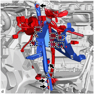
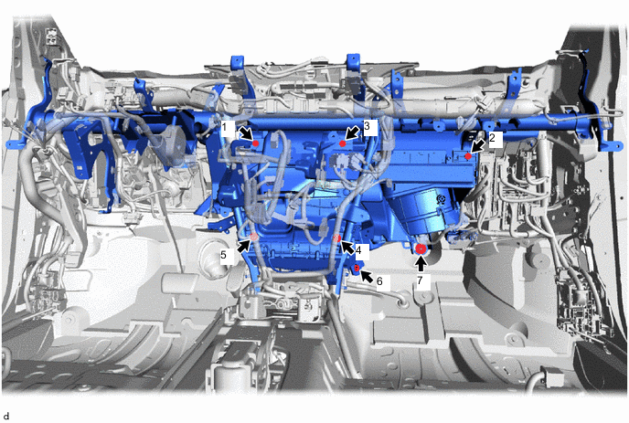
CONNECT INLET HEATER WATER HOSE A
-
*a View A *b Marking (yellow) *c Clip Installation Angle (90°) With the marking facing the right side of the vehicle, connect inlet heater water hose A, and install the clip in the area shown in the illustration.
Note
-
Do not apply excessive force to inlet heater water hose A.
-
Install the heater water hose A first.
-
-
-
CONNECT OUTLET HEATER WATER HOSE
-
*a View A *b Marking (White) *c Clip Installation Angle (90°) With the marking facing the right side of the vehicle, connect outlet heater water hose, and install the clip in the area shown in the illustration.
Note
Do not apply excessive force to outlet heater water hose.
-
-
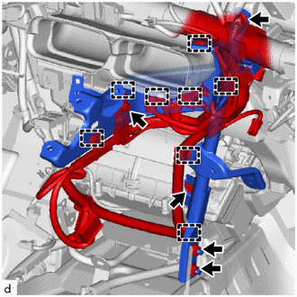
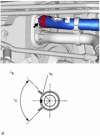
CONNECT AIRCONDITIONER TUBE AND ACCESSORY ASSEMBLY
-
Remove the vinyl tape from the airconditioner tube and accessory assembly and the cooler expansion valve.
-
Apply sufficient compressor oil to 2 new O-rings and fitting surfaces of the airconditioner tube and accessory assembly.
Compressor Oil ND-OIL 12 or equivalent -
Install the 2 O-rings to the airconditioner tube and accessory assembly.
Note
Keep the O-rings and O-ring fitting surfaces free of foreign matter.
-
Connect the air conditioner tube and accessory assembly by pushing it in until it securely engages.
-
Install in this Direction As shown in the illustration, rotate the hook-shaped connector to the fastening position, and fasten it with the bolt.
- Torque:
- 9.8 N*m { 100 kgf*cm, 87 in.*lbf }
-
-
INSTALL OUTER COWL TOP PANEL SUB-ASSEMBLY
-
INSTALL COWL BODY MOUNTING REINFORCEMENT RH
-
INSTALL WATER GUIDE PLATE LH
-
INSTALL NO. 2 HEATER AIR DUCT SPLASH SHIELD SEAL
-
INSTALL WINDSHIELD WIPER MOTOR AND LINK
-
ADD COOLANT (FC STACK COOLANT)
-
INSPECT FOR COOLANT (FC STACK COOLANT) LEAK
-
INSTALL SUSPENSION MEMBER TO FRONT CROSSMEMBER BRACE SUB-ASSEMBLY
-
INSTALL FRONT FLOOR COVER RH
-
INSTALL FRONT FLOOR COVER LH
-
INSTALL NO. 2 MOTOR UNDER COVER
-
INSTALL FRONT BUMPER LOWER ABSORBER
-
CHARGE AIR CONDITIONING SYSTEM WITH REFRIGERANT
-
WARM UP COMPRESSOR
-
INSPECT FOR REFRIGERANT LEAK
-
INITIALIZE INITIALIZATION SERVO MOTOR