AIR CONDITIONING UNIT REMOVAL
CAUTION / NOTICE / HINT
CAUTION:
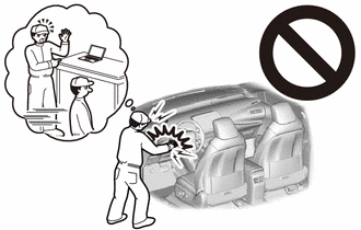
Some of these service operations affect the SRS airbag system. Read the precautionary notices concerning the SRS airbag system before servicing.
Note
After turning the power switch off, waiting time may be required before disconnecting the cable from the auxiliary battery negative (-) terminal. Therefore, make sure to read the disconnecting the cable from the auxiliary battery negative (-) terminal notices before proceeding with work.
PROCEDURE
-
CAUTION
Note
-
The coolant (Toyota genuine FC stack coolant) is an exclusive coolant.
-
The coolant (Toyota genuine FC stack coolant) cannot be reused, so when filling, be sure to fill with new coolant (Toyota genuine FC stack coolant).
-
To prevent degradation of coolant (Toyota genuine FC stack coolant) performance, do not add or fill any other substances such as tap water or battery electrolyte refill liquid.
-
Do not use cotton work gloves or other gloves that could shed fibers.
-
DO NOT use any container that has previously been used to fill substances such as oil.
-
To prevent foreign matter from contaminating the coolant (Toyota genuine FC stack coolant) passages, wash out the prepared container with tap water, then wipe away any water remaining inside the container before using it.
-
If the coolant (Toyota genuine FC stack coolant) passages are filled incorrectly, follow the countermeasures according to "Countermeasures when coolant (Toyota genuine FC stack coolant) passages are filled incorrectly".
-
When the vehicle is parked with the power switch off, if the FC control ECU judges that the FC stack temperature will go below 0°C, it activates the FC air compressor, hydrogen pump and FC cooling water pump for a maximum of 180 seconds and drains water from the FC stack assembly. When performing inspection or repairs with the power switch off (not on (IG) or on (READY)), disconnect the cable from the negative auxiliary battery terminal before performing work.
-
-
RECOVER REFRIGERANT FROM REFRIGERATION SYSTEM
-
REMOVE FRONT BUMPER LOWER ABSORBER
-
REMOVE NO. 2 MOTOR UNDER COVER
-
REMOVE FRONT FLOOR COVER LH
-
REMOVE FRONT FLOOR COVER RH
-
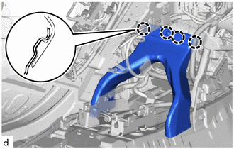
REMOVE SUSPENSION MEMBER TO FRONT CROSSMEMBER BRACE SUB-ASSEMBLY
-
DRAIN COOLANT (FC STACK COOLANT)
-
REMOVE WINDSHIELD WIPER MOTOR AND LINK
-
REMOVE NO. 2 HEATER AIR DUCT SPLASH SHIELD SEAL
-
REMOVE WATER GUIDE PLATE LH
-
REMOVE COWL BODY MOUNTING REINFORCEMENT RH
-
REMOVE OUTER COWL TOP PANEL SUB-ASSEMBLY
-
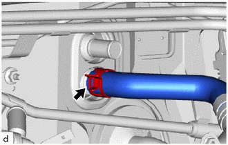
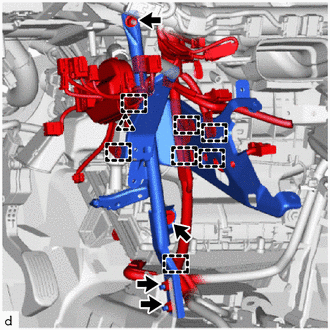
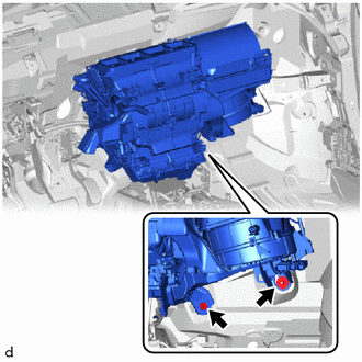
DISCONNECT AIRCONDITIONER TUBE AND ACCESSORY ASSEMBLY
-
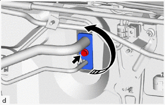

Remove in this Direction Remove the bolt and rotate the hook connector as shown in the illustration.
-
Disconnect the air conditioner tube and accessory assembly.
-
Remove the 2 O-rings from the air conditioner tube and accessory assembly.
Note
Seal the openings of the disconnected parts using vinyl tape to prevent entry of moisture and foreign matter.
-
-
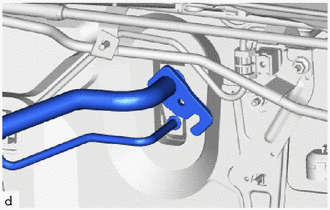
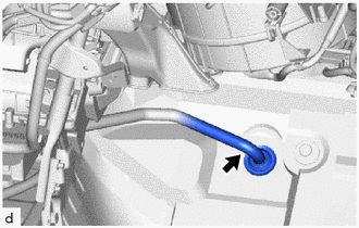
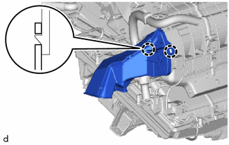
DISCONNECT OUTLET HEATER WATER HOSE
-
Slide the hose clip to disconnect the outlet heater water hose.
Note
-
To prevent contamination by foreign matter or water droplets, protect the connecting portions of the outlet heater water hose and air conditioner radiator assembly with plastic bags.
-
Do not apply excessive force to the outlet heater water hose.
-
Prepare a drain pan or cloth in case the coolant leaks.
-
-
-
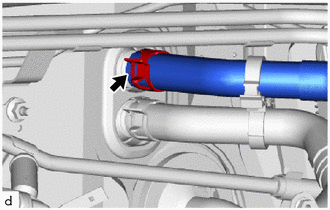
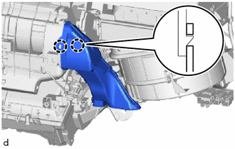
DISCONNECT INLET HEATER WATER HOSE A
-
Slide the hose clip to disconnect the inlet heater water hose A.
Note
-
To prevent contamination by foreign matter or water droplets, protect the connecting portions of the inlet heater water hose A and air conditioner radiator assembly with plastic bags.
-
Do not apply excessive force to the inlet heater water hose A.
-
Prepare a drain pan or cloth in case the coolant leaks.
-
-
-
REMOVE UPPER INSTRUMENT PANEL SUB-ASSEMBLY
-
REMOVE FRONT SEAT ASSEMBLY LH
-
REMOVE STEERING COLUMN ASSEMBLY
-
REMOVE POWER STEERING ECU ASSEMBLY
-
REMOVE COOLER BLOWER ASSEMBLY
-
REMOVE REAR NO. 5 AIR DUCT
-
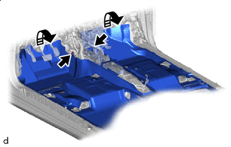
Remove in this Direction Remove the 2 clips.
-
Remove each fastener for fitting and turn over the floor carpet assembly front on the front end in the area where removal and installation work can be done.
-
Remove the clip.
-
Disengage the claws to remove the rear No. 5 air duct.
-
-
REMOVE REAR NO. 3 AIR DUCT
Tech Tips
Use the same procedure for the RH side and LH side.
-
REMOVE REAR NO. 4 AIR DUCT
-
Disengage the claws to remove the rear No. 4 air duct.
-
-
REMOVE REAR NO. 2 AIR DUCT
Tech Tips
Use the same procedure for the RH side and LH side.
-
REMOVE REAR NO. 1 AIR DUCT
-
Disengage the claws to remove the rear No. 1 air duct.
-
-
SEPARATE DRAIN COOLER HOSE
-
Separate the drain cooler hose.
-
-
REMOVE TRANSMISSION INSTRUMENT PANEL SHIFT ASSEMBLY
-
REMOVE CENTER LOWER CLUSTER SUPPORT BRACKET
-
Remove the 4 bolts and center lower cluster support bracket.
-
-
REMOVE WINDSHIELD WIPER RELAY ASSEMBLY
-
REMOVE NO. 1 INSTRUMENT PANEL BRACE SUB-ASSEMBLY
-
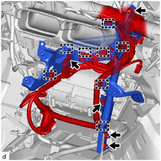
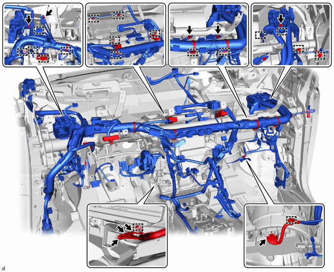
Disengage the clamps to separate the wire harness.
-
Remove the 3 nuts and screw and No. 1 instrument panel brace sub-assmbly.
-
-
REMOVE NO. 2 INSTRUMENT PANEL BRACE SUB-ASSEMBLY
-
Remove the bolt to separate the ground wire.
-
Disengage the clamps to separate the wire harness.
-
Remove the 3 nuts and screw and No. 2 instrument panel brace sub-assembly.
-
-
REMOVE NO. 2 HEATER TO REGISTER DUCT
-
Disengage the clamps.
-
Remove the 7 clips and No. 2 heater to register duct .
-
-
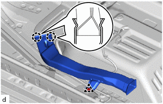
REMOVE LOWER DEFROSTER NOZZLE ASSEMBLY
-
Remove in this Direction Disengage the clamp.
-
Disengage the claws to remove the lower defroster nozzle assembly as shown in the illustration.
-
-
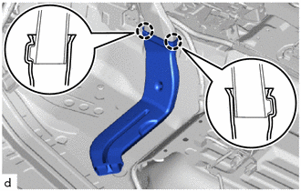
REMOVE DEFROSTER NOZZLE ASSEMBLY
-
Disengage the guides to remove the defroster nozzle assembly.
-
-
REMOVE NO. 3 AIR DUCT SUB-ASSEMBLY
-
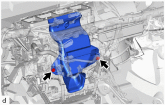
Remove the 2 nuts and No. 3 air duct sub-assembly.
-
-
REMOVE ECU INTEGRATION BOX LH
-
REMOVE INSTRUMENT PANEL JUNCTION BLOCK ASSEMBLY
-
REMOVE ECU INTEGRATION BOX RH
-
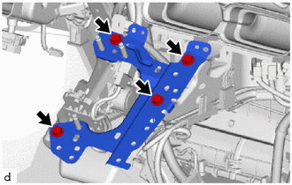
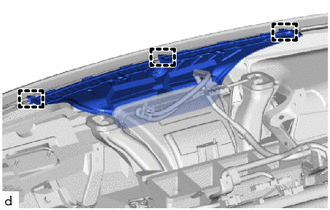
REMOVE INSTRUMENT PANEL REINFORCEMENT ASSEMBLY
-
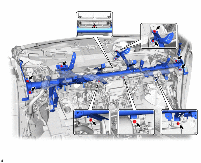
Disconnect the 4 connectors.
-
Remove the 3 bolts and ground wire.
-
Remove the 2 bolts.
-
Disengage the clamps to separate the instrument wire.
-
Remove the 9 bolts and clip and instrument panel reinforcement assembly.
-
-
REMOVE NO. 4 HEATER TO REGISTER DUCT
-
Remove the 2 clips and No. 4 heater to register duct.
-
-
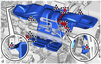
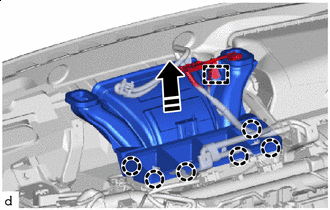
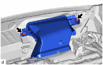
REMOVE AIR CONDITIONER UNIT ASSEMBLY
Note
-
Be sure to support the air conditioning unit assembly when removing it because failure to do so may cause the bracket of the air conditioning unit assembly to break.
-
When disassembling the air conditioning unit assembly, eliminate static electricity by touching the vehicle body to prevent the components from being damaged.
-
Remove the bolt and nut and air conditioner unit assembly.
-
-
REMOVE NO. 1 AIR DUCT SUB-ASSEMBLY
-
Disengage the claws to remove the No. 1 air duct sub-assembly.
Note
-
When removing, do not crack or deform the upper heater case of the air conditioning radiator assembly.
-
If the No. 1 air duct sub-assembly is reused, it may fall off or abnormal noise may occur. Therefore, make sure to replace with a new one.
-
-
-
REMOVE NO. 2 AIR DUCT SUB-ASSEMBLY
-
Disengage the claws to remove the No. 2 air duct sub-assembly.
Note
-
When removing, do not crack or deform the upper heater case of the air conditioning radiator assembly.
-
If the No. 2 air duct sub-assembly is reused, it may fall off or abnormal noise may occur. Therefore, make sure to replace with a new one.
-
-