AIR CONDITIONING SYSTEM Rear Blower Motor Circuit
DESCRIPTION
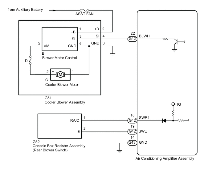
The cooler blower assembly is operated by signals from the air conditioning amplifier assembly. Rear blower motor speed signals are transmitted in accordance with changes in the duty ratio.
WIRING DIAGRAM
CAUTION / NOTICE / HINT
Note
Inspect the fuses for circuits related to this system before performing the following procedure.
PROCEDURE
-
PERFORM ACTIVE TEST USING GTS
-
Connect the GTS to the DLC3.
-
Turn the power switch on (IG).
-
Turn the GTS on.
-
Enter the following menus: Body Electrical / Air Conditioner / Active Test.
-
Check the operation by referring to the table below.
Body Electrical > Air Conditioner > Active TestTester Display Measurement Item Control Range Diagnostic Note Assist Fan Cooler blower assembly Min.: 0
Max.: 31
-
Body Electrical > Air Conditioner > Active TestTester Display Assist Fan Result Result Proceed to OK A NG (Cooler blower assembly does not operate) B NG (Cooler blower assembly operates but does not change speed) C
B 
INSPECT COOLER BLOWER ASSEMBLY (COOLER BLOWER MOTOR) Click here
C
GO TO STEP 9 Click here
A 
-
-
READ VALUE USING GTS
-
Connect the GTS to the DLC3.
-
Turn the power switch on (IG).
-
Turn the GTS on.
-
Enter the following menus: Body Electrical / Air Conditioner / Data List.
-
Check the value(s) by referring to the table below.
Body Electrical > Air Conditioner > Data ListTester Display Measurement Item Range Normal Condition Diagnostic Note Rear FACE Shut Switch Console box resistor assembly (rear blower switch) ON or OFF ON: Console box resistor assembly (rear blower switch) ON
OFF: Console box resistor assembly (rear blower switch) OFF
-
Body Electrical > Air Conditioner > Data ListTester Display Rear FACE Shut Switch OK The display is as specified in the normal condition column. Result Proceed to OK NG
OK 
PROCEED TO NEXT SUSPECTED AREA SHOWN IN PROBLEM SYMPTOMS TABLE Click here
NG
-
-
INSPECT CONSOLE BOX RESISTOR ASSEMBLY (REAR BLOWER SWITCH)
-
Remove the console box resistor assembly (rear blower switch).
-
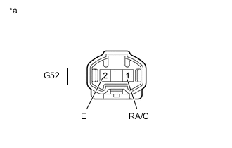
*a Component without harness connected
(Console Box Resistor Assembly (Rear Blower Switch))
Measure the resistance according to the value(s) in the table below.
Standard Resistance Tester Connection Switch Condition Specified Condition G52-1 (RA/C) - G52-2 (E) Rear blower switch off 10 kΩ or higher Rear blower switch on Below 1 Ω Result Proceed to OK NG
NG
REPLACE CONSOLE BOX RESISTOR ASSEMBLY (REAR BLOWER SWITCH) Click here
OK
-
-
CHECK HARNESS AND CONNECTOR (CONSOLE BOX RESISTOR ASSEMBLY (REAR BLOWER SWITCH) - AIR CONDITIONING AMPLIFIER ASSEMBLY)
-
Disconnect the G52 console box resistor assembly (rear blower switch) connector.
-
Disconnect the G42 air conditioning amplifier assembly connector.
-
Measure the resistance according to the value(s) in the table below.
Standard Resistance Tester Connection Condition Specified Condition G52-1 (RA/C) - G42-18 (SWR1) Always Below 1 Ω G52-2 (E) - G42-19 (SWE) Always Below 1 Ω G52-1 (RA/C) or G42-18 (SWR1) - Body ground Always 10 kΩ or higher G52-2 (E) or G42-19 (SWE) - Body ground Always 10 kΩ or higher Result Proceed to OK NG
OK
REPLACE AIR CONDITIONING AMPLIFIER ASSEMBLY Click here
NG
REPAIR OR REPLACE HARNESS OR CONNECTOR
-
-
INSPECT COOLER BLOWER ASSEMBLY (COOLER BLOWER MOTOR)
-
Remove the cooler blower assembly (cooler blower motor).
-
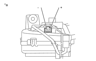
*a Component without harness connecter
Cooler Blower Assembly (Cooler Blower Motor)
Check the cooler blower assembly (cooler blower motor) operation.
OK Tester Connection Condition Specified Condition C-2 (+) - C-1 (-) Connect the auxiliary battery positive (+) - 2
Connect the auxiliary battery negative (-) - 1
Cooler blower motor operates smoothly Result Proceed to OK NG
NG
REPAIR COOLER BLOWER ASSEMBLY Click here
OK
-
-
CHECK HARNESS AND CONNECTOR (COOLER BLOWER ASSEMBLY - POWER SOURCE CIRCUIT)
-
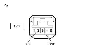
*a Front view of wire harness connector
(to Cooler Blower Assembly)
Disconnect the cooler blower assembly connector.
-
Measure the resistance according to the value(s) in the table below.
Standard Resistance Tester Connection Condition Specified Condition G51-3 (GND) - Body ground Always Below 1 Ω -
Measure the voltage according to the value(s) in the table below.
Standard Voltage Tester Connection Switch Condition Specified Condition G51-2 (+B) - Body ground Power switch on (IG) 11 to 14 V Result Proceed to OK NG
NG
REPAIR OR REPLACE HARNESS OR CONNECTOR
OK
-
-
INSPECT COOLER BLOWER ASSEMBLY
-
Remove the cooler blower assembly.
-
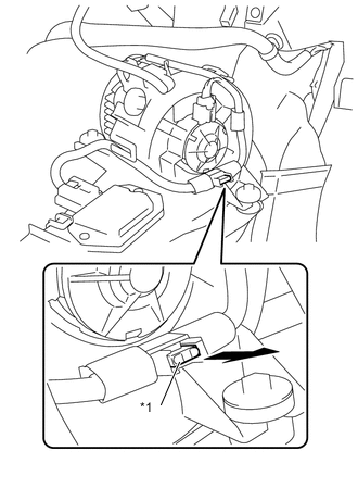
*1 D Fuse Measure the resistance according to the value(s) in the table below.
Standard Resistance Tester Connection Condition Specified Condition D Fuse Always Below 1 Ω -
Disconnect the B blower motor control connector.
-
Disconnect the C cooler blower motor connector.
-
Measure the resistance according to the value(s) in the table below.
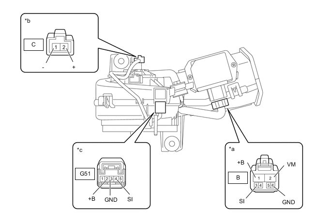
*a Component without harness connected
(Blower Motor Control)
*b Component without harness connected
(Cooler Blower Motor)
*c Component without harness connected
(Cooler Blower Assembly)
- - Standard Resistance Tester Connection Condition Specified Condition B-1 (+B) - G51-2 (+B) Always Below 1 Ω B-3 (SI) - G51-4 (SI) Always Below 1 Ω B-6 (GND) - G51-3 (GND) Always Below 1 Ω B-6 (GND) - C-1 (-) Always Below 1 Ω B-2 (VM) - C-2 (+) Always Below 1 Ω Result Proceed to OK NG
NG
REPAIR COOLER BLOWER ASSEMBLY Click here
OK
-
-
CHECK HARNESS AND CONNECTOR (COOLER BLOWER ASSEMBLY - AIR CONDITIONING AMPLIFIER ASSEMBLY)
-
Disconnect the G51 cooler blower assembly connector.
-
Disconnect the G42 air conditioning amplifier assembly connector.
-
Measure the resistance according to the value(s) in the table below.
Standard Resistance Tester Connection Condition Specified Condition G51-4 (SI) - G42-22 (BLWH) Always Below 1 Ω G51-4 (SI) or G42-22 (BLWH) - Body ground Always 10 kΩ or higher Result Proceed to OK NG
NG
REPAIR OR REPLACE HARNESS OR CONNECTOR
OK
-
-
INSPECT AIR CONDITIONING AMPLIFIER ASSEMBLY
-
Reconnect the G42 air conditioning amplifier assembly connector.
-
Turn the power switch on (IG).
-
Turn the rear blower switch on (LO).
-
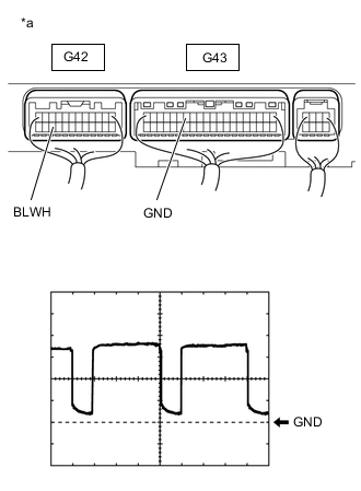
*a Component with harness connected
(Air Conditioning Amplifier Assembly)
Measure the waveform between terminal G42-22 (BLWH) of the air conditioning amplifier assembly and body ground.
OK Waveform is similar to that shown in the illustration. Tech Tips
The waveform varies with the blower speed.
Item Content Tool setting 2 V/DIV., 500 μs/DIV. Vehicle condition
-
Power switch on (IG)
-
Rear blower switch: LO
Result Proceed to OK NG -
OK
REPLACE BLOWER MOTOR CONTROL Click here
NG
REPLACE AIR CONDITIONING AMPLIFIER ASSEMBLY Click here
-