AIR CONDITIONING SYSTEM, Diagnostic DTC:B1414/14
| DTC Code | DTC Name |
|---|---|
| B1414/14 | Water Temperature Circuit |
DESCRIPTION
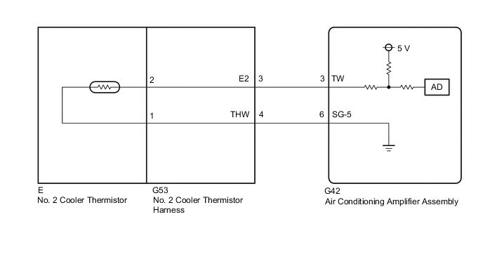
The No. 2 Cooler Thermistor is installed in the heater radiator unit sub-assembly to detect the water temperature which is used to control the heater and air conditioning system heater mode. The resistance of the No. 2 cooler thermistor changes in accordance with the water temperature. As the temperature decreases, the resistance increases. As the temperature increases, the resistance decreases.
The air conditioning amplifier assembly applies a voltage (5 V) to the No. 2 cooler thermistor and reads voltage changes due to changes in the resistance of the No. 2 Cooler Thermistor.
| DTC No. | Detection Item | DTC Detection Condition | Trouble Area | Memory |
|---|---|---|---|---|
| B1414/14 | Water Temperature Circuit | Any of the following conditions is met:
|
|
Memorized (4 seconds or more) |
Tech Tips
The air conditioning amplifier assembly stores the DTC of the respective malfunction if it has occurred for the period of time indicated in the brackets.
| Vehicle Condition | |||
|---|---|---|---|
| Pattern 1 | Pattern 2 | ||
| Diagnosis Condition | Power switch on (IG) | ○ | ○ |
| Malfunction Status | Open in No. 2 cooler thermistor circuit | ○ | - |
| Short in No. 2 cooler thermistor circuit | - | ○ | |
| Detection Time | 4 seconds or more | 4 seconds or more | |
| Number of Trips | 1 trip | 1 trip | |
Tech Tips
DTC will be output when conditions for either of the patterns in the table above are met.
WIRING DIAGRAM
PROCEDURE
-
READ VALUE USING GTS
-
Connect the GTS to the DLC3.
-
Turn the power switch on (IG).
-
Turn the GTS on.
-
Enter the following menus: Body Electrical / Air Conditioner / Data List.
-
Check the value(s) by referring to the table below.
Body Electrical > Air Conditioner > Data ListTester Display Measurement Item Range Normal Condition Diagnostic Note Engine Coolant Temp Heater core inlet water temperature Min.: 1.30°C (34.34°F)
Max.: 90.55°C (194.99°F)
Heater pipe (electric heater sub-assembly to heater radiator unit sub-assembly) temperature displayed -
Body Electrical > Air Conditioner > Data ListTester Display Engine Coolant Temp OK The display is as specified in the normal condition column. Result Result Proceed to OK (When troubleshooting according to Problem Symptoms Table) A OK (When troubleshooting according to the DTC) B NG C
A 
PROCEED TO NEXT SUSPECTED AREA SHOWN IN PROBLEM SYMPTOMS TABLE Click here
B
REPLACE AIR CONDITIONING AMPLIFIER ASSEMBLY Click here
C 
-
-
INSPECT NO. 2 COOLER THERMISTOR
-
Remove the No. 2 cooler thermistor.
-
Inspect the No. 2 cooler thermistor.
Result Proceed to OK NG
NG
REPLACE NO. 2 COOLER THERMISTOR Click here
OK
-
-
CHECK NO. 2 COOLER THERMISTOR HARNESS
-
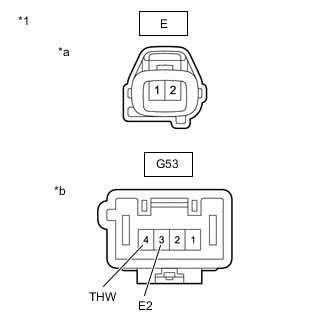
*1 No. 2 Cooler Thermistor Harness *a Front view of air conditioning harness assembly
(to No. 2 Cooler Thermistor)
*b Front view of air conditioning harness assembly
(to Wire Harness)
Disconnect the No. 2 cooler thermistor harness.
-
Measure the resistance according to the value(s) in the table below.
Standard Resistance Tester Connection Condition Specified Condition E-2 - G53-3 (E2) Always Below 1 Ω E-1 - G53-4 (THW) Always Below 1 Ω E-2 or G53-3 (E2) - Body ground Always 10 kΩ or higher E-1 or G53-4 (THW) - Body ground Always 10 kΩ or higher Result Proceed to OK NG
NG
REPLACE NO. 2 COOLER THERMISTOR HARNESS Click here
OK
-
-
CHECK HARNESS AND CONNECTOR (NO. 2 COOLER THERMISTOR HARNESS - AIR CONDITIONING AMPLIFIER ASSEMBLY)
-
Disconnect the G53 No. 2 cooler thermistor harness connector.
-
Disconnect the G42 air conditioning amplifier assembly connector.
-
Measure the resistance according to the value(s) in the table below.
Standard Resistance Tester Connection Condition Specified Condition G53-4 (THW) - G42-6 (SG-5) Always Below 1 Ω G53-3 (E2) - G42-3 (TW) Always Below 1 Ω G53-4 (THW) or G42-6 (SG-5) - Body ground Always 10 kΩ or higher G53-3 (E2) or G42-3 (TW) - Body ground Always 10 kΩ or higher Result Proceed to OK NG
OK
REPLACE AIR CONDITIONING AMPLIFIER ASSEMBLY Click here
NG
REPAIR OR REPLACE HARNESS OR CONNECTOR
-