AIR CONDITIONING SYSTEM, Diagnostic DTC:B14AB
| DTC Code | DTC Name |
|---|---|
| B14AB | Heating Three-way Valve Circuit |
DESCRIPTION
The electromagnetic valve of the 3-way valve is opened and closed according to air conditioning amplifier assembly control, changing the FC coolant flow modes (Independent / Intermediate / Linked).
| DTC No. | Detection Item | DTC Detection Condition | Trouble Area | Memory |
|---|---|---|---|---|
| B14AB | Heating Three-way Valve Circuit | During 3 way valve operation, the heating 3-way valve operation request signal is output for 10 seconds or more, but the actual position information of the heating 3 way valve has not reached the target position. |
|
Memorized (10 seconds or more) |
Tech Tips
The air conditioning amplifier assembly stores this DTC if the malfunction has occurred for the period of time indicated in the parentheses.
WIRING DIAGRAM
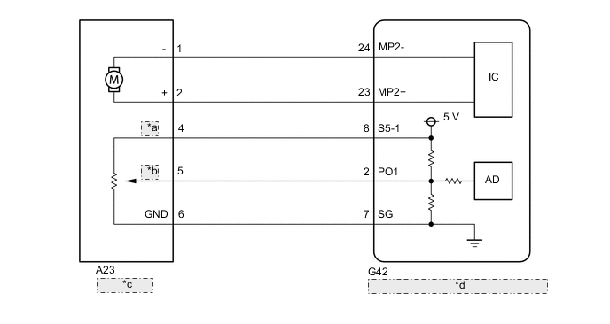
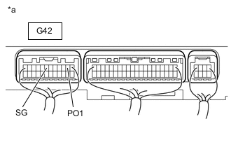
| *a | WVO |
| *b | WVS |
| *c | 3 Way Valve |
| *d | Air Conditioning Amplifier Assembly |
PROCEDURE
-
PERFORM ACTIVE TEST USING GTS
-
Remove the air conditioning amplifier assembly with connectors still connected.
-
Connect the GTS to the DLC3.
-
Turn the power switch on (IG).
-
Enter the following menus: Body Electrical / Air Conditioner / Active Test.
-
Check the operation by referring to the table below.
Body Electrical > Air Conditioner > Active TestTester Display Measurement Item Control Range Diagnostic Note Heater Valve 3 way valve Close, Half, Open -
Body Electrical > Air Conditioner > Active TestTester Display Heater Valve -
*a Component with harness connected
(to Air Conditioning Amplifier Assembly)
Measure the voltage according to the value(s) in the table below.
Standard Voltage Tester Connection Condition Specified Condition G42-2 (PO1) - G42-7 (SG) Active Test "Close" 2.3 to 2.7 V Active Test "Half" 1.3 to 1.7 V Active Test "Open" 0.3 to 0.7 V Result Result Proceed to OK (When troubleshooting according to Problem Symptoms Table) A OK (When troubleshooting according to the DTC) B NG C
A 
PROCEED TO NEXT SUSPECTED AREA SHOWN IN PROBLEM SYMPTOMS TABLE Click here
B
REPLACE AIR CONDITIONING AMPLIFIER ASSEMBLY Click here
C 
-
-
CHECK HARNESS AND CONNECTOR (3 WAY VALVE - AIR CONDITIONING AMPLIFIER ASSEMBLY)
-
Disconnect the A23 3 way valve connector.
-
Disconnect the G42 air conditioning amplifier assembly connector.
-
Measure the resistance according to the value(s) in the table below.
Standard Resistance Tester Connection Condition Specified Condition A23-1(-) - G42-24(MP2-) Always Below 1 Ω A23-2(+) - G42-23(MP2+) Always Below 1 Ω A23-4(WVO) - G42-8(S5-1) Always Below 1 Ω A23-5(WVS) - G42-2(PO1) Always Below 1 Ω A23-6(GND) - G42-7(SG) Always Below 1 Ω A23-1 (-) or G42-24 (MP2-) - Body ground Always 10 kΩ or higher A23-2 (+) or G42-23 (MP2+) - Body ground Always 10 kΩ or higher A23-4 (WVO) or G42-8 (S5-1) - Body ground Always 10 kΩ or higher A23-5 (WVS) or G42-2 (PO1) - Body ground Always 10 kΩ or higher A23-6 (GND) or G42-7 (SG) - Body ground Always 10 kΩ or higher Result Proceed to OK NG
NG
REPAIR OR REPLACE HARNESS OR CONNECTOR
OK
-
-
CHECK 3 WAY VALVE
-
Replace the 3 way valve with a new or known good one.
-
Clear the DTCs.
Body Electrical > Air Conditioner > Clear DTCs -
Check for DTCs.
Body Electrical > Air Conditioner > Trouble CodesOK DTC B14AB is not output. Result Proceed to OK NG
OK
END (3 WAY VALVE WAS DEFECTIVE)
NG
REPLACE AIR CONDITIONING AMPLIFIER ASSEMBLY Click here
-