AIR CONDITIONING SYSTEM, Diagnostic DTC:B14AA
| DTC Code | DTC Name |
|---|---|
| B14AA | Glass Humidity Sensor Circuit |
DESCRIPTION
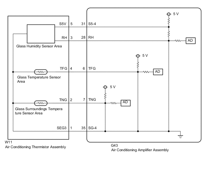
The air conditioning thermistor assembly (glass humidity sensor) detects cabin humidity. The voltage of the air conditioning thermistor assembly (glass humidity sensor) changes in accordance with cabin humidity. The air conditioning amplifier assembly reads the changes in output voltage of the air conditioning thermistor assembly (glass humidity sensor).
The glass humidity sensor is integrated with the air conditioning thermistor assembly.
| DTC No. | Detection Item | DTC Detection Condition | Trouble Area | Memory |
|---|---|---|---|---|
| B14AA | Glass Humidity Sensor Circuit | Any of the following conditions is met:
|
|
Memorized (4 seconds or more) |
Tech Tips
The air conditioning amplifier assembly stores this DTC if the malfunction has occurred for the period of time indicated in the brackets.
| Vehicle Condition | |||
|---|---|---|---|
| Pattern 1 | Pattern 2 | ||
| Diagnosis Condition | Power switch on (IG) | ○ | ○ |
| Malfunction Status | Open in glass humidity sensor circuit | ○ | - |
| Short in glass humidity sensor circuit | - | ○ | |
| Detection Time | 4 seconds or more | 4 seconds or more | |
| Number of Trips | 1 trip | 1 trip | |
Tech Tips
DTC will be output when conditions for either of the patterns in the table above are met.
WIRING DIAGRAM
CAUTION / NOTICE / HINT
Tech Tips
The air conditioning thermistor assembly must be replaced if the glass humidity sensor is malfunctioning.
PROCEDURE
-
READ VALUE USING GTS
-
Connect the GTS to the DLC3.
-
Turn the power switch on (IG).
-
Turn the GTS on.
-
Enter the following menus: Body Electrical / Air Conditioner / Data List.
-
Check the value(s) by referring to the table below.
Body Electrical > Air Conditioner > Data ListTester Display Measurement Item Range Normal Condition Diagnostic Note Glass Humidity Glass humidity Min.: 0.00%
Max.: 100.00%
Actual glass humidity is displayed -
Body Electrical > Air Conditioner > Data ListTester Display Glass Humidity OK The display is as specified in the normal condition column. Result Result Proceed to NG A OK (When troubleshooting according to Problem Symptoms Table) B OK (When troubleshooting according to the DTC) C
B 
PROCEED TO NEXT SUSPECTED AREA SHOWN IN PROBLEM SYMPTOMS TABLE Click here
C
REPLACE AIR CONDITIONING AMPLIFIER ASSEMBLY Click here
A 
-
-
CHECK HARNESS AND CONNECTOR (POWER SOURCE CIRCUIT)
-
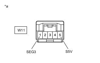
*a Front view of wire harness connector
(to Air Conditioning Thermistor Assembly (Glass Humidity Sensor))
Disconnect the air conditioning thermistor assembly (glass humidity sensor) connector.
-
Measure the voltage according to the value(s) in the table below.
Standard Voltage Tester Connection Condition Specified Condition W11-5 (S5V) - Body ground Power switch off Below 1 V W11-5 (S5V) - Body ground Power switch on (IG) 4.5 to 5.5 V Result Proceed to OK NG
NG 
CHECK HARNESS AND CONNECTOR (AIR CONDITIONING THERMISTOR ASSEMBLY (GLASS HUMIDITY SENSOR) - AIR CONDITIONING AMPLIFIER ASSEMBLY) Click here
OK
-
-
INSPECT AIR CONDITIONING THERMISTOR ASSEMBLY (GLASS HUMIDITY SENSOR)
-
Remove the air conditioning thermistor assembly (glass humidity sensor).
-
Inspect the air conditioning thermistor assembly (glass humidity sensor).
Result Proceed to OK NG
NG
REPLACE AIR CONDITIONING THERMISTOR ASSEMBLY (GLASS TEMPERATURE SENSOR) Click here
OK
-
-
CHECK HARNESS AND CONNECTOR (AIR CONDITIONING THERMISTOR ASSEMBLY (GLASS HUMIDITY SENSOR) - AIR CONDITIONING AMPLIFIER ASSEMBLY)
-
Disconnect the W11 air conditioning thermistor assembly (glass humidity sensor) connector.
-
Disconnect the G43 air conditioning amplifier assembly connector.
-
Measure the resistance according to the value(s) in the table below.
Standard Resistance Tester Connection Condition Specified Condition W11-3 (RH) - G43-28 (RH) Always Below 1 Ω W11-3 (RH) or G43-28 (RH) - Body ground Always 10 kΩ or higher Result Proceed to OK NG
OK
REPLACE AIR CONDITIONING AMPLIFIER ASSEMBLY Click here
NG
REPAIR OR REPLACE HARNESS OR CONNECTOR
-
-
CHECK HARNESS AND CONNECTOR (AIR CONDITIONING THERMISTOR ASSEMBLY (GLASS HUMIDITY SENSOR) - AIR CONDITIONING AMPLIFIER ASSEMBLY)
-
Disconnect the W11 air conditioning thermistor assembly (glass humidity sensor) connector.
-
Disconnect the G43 air conditioning amplifier assembly connector.
-
Measure the resistance according to the value(s) in the table below.
Standard Resistance Tester Connection Condition Specified Condition W11-1 (SEG3) - G43-35 (SG-4) Always Below 1 Ω W11-5 (S5V) - G43-31 (S5-4) Always Below 1 Ω W11-1 (SEG3) or G43-35 (SG-4) - Body ground Always 10 kΩ or higher W11-5 (S5V) or G43-31 (S5-4) - Body ground Always 10 kΩ or higher Result Proceed to OK NG
OK
REPLACE AIR CONDITIONING AMPLIFIER ASSEMBLY Click here
NG
REPAIR OR REPLACE HARNESS OR CONNECTOR
-