AIR CONDITIONING SYSTEM TERMINALS OF ECU
-
AIR CONDITIONING AMPLIFIER ASSEMBLY
-
Disconnect the air conditioning amplifier assembly connector.
-
Measure the resistance and voltage according to the value(s) in the table below.
Tech Tips
Check from the rear of the connector while it is connected to the air conditioning amplifier assembly.
Terminal No.
(Symbol)
Wiring Color Terminal Description Condition Specified Condition G43-1 (IG+) - Body ground B - Body ground Power source (IG) Power switch on (IG) 11 to 14 V Power switch off Below 1 V G43-14 (GND) - Body ground W-B - Body ground Ground for main power supply Always Below 1 Ω G43-21 (B) - Body ground GR - Body ground Power source (Back-up) Power switch off 11 to 14 V -
Reconnect the air conditioning amplifier assembly connector.
-
Measure the resistance, voltage and waveform according to the value(s) in the table below.
Tech Tips
Check from the rear of the connector while it is connected to the air conditioning amplifier assembly.
Terminal No.
(Symbol)
Wiring Color Terminal Description Condition Specified Condition G42-2 (PO1) - G42-7 (SG) SB - G 3 way valve position signal
-
Power switch on (IG)
-
3 way valve mode alone
2.3 to 2.7 V
-
Power switch on (IG)
-
3 way valve mode cooperation
0.3 to 0.7 V G42-3 (TW) - G42-6 (SG-5) G - P FC water temperature sensor signal
-
Power switch on (IG)
-
FC water temperature 25°C (77°F)
1.3 to 1.7 V
-
Power switch on (IG)
-
FC water temperature 40°C (104°F)
0.8 to 1.2 V G42-6 (SG-5) - Body ground P - Body ground Ground for water temperature sensor Always Below 1 Ω G42-7 (SG) - Body ground G - Body ground Ground for 3 way valve Always Below 1 Ω G42-8 (S5-1) - G43-14 (GND) L - W-B Power source of 3 way valve Power switch on (IG) 4.75 to 5.25 V G42-18 (SWR1) - G42-19 (SWE) BE - V Rear blower switch signal
-
Power switch on (IG)
-
Rear blower switch on
Below 1 V
-
Power switch on (IG)
-
Rear blower switch off
11 to 14 V G42-19 (SWE) - Body ground V - Body ground Ground for rear blower switch Always Below 1 Ω G42-22 (BLWH) - G43-14 (GND) Y - W-B Rear blower motor operation signal
-
Power switch on (IG)
-
Rear blower switch LO
Pulse generation
(See Waveform 1)
G42-23 (MP2+) - G43-14 (GND) B - W-B 3 way valve operation signal
-
Power switch on (IG)
-
3 way valve mode cooperation → alone
Below 1 V → 11 to 14 V → Below 1 V G42-24 (MP2-) - G43-14 (GND) R - W-B 3 way valve operation signal
-
Power switch on (IG)
-
3 way valve mode alone → cooperation
Below 1 V → 11 to 14 V → Below 1 V G43-3 (PTC3) - G43-14 (GND)*1 BR - W-B Quick heater assembly operation signal
-
Power switch on (READY)
-
ECO mode switch off
-
Temperature settings: MAX HOT
-
Ambient temperature: 10°C (50°F) or lower
-
FC coolant temperature: 65°C (149°F) or lower
-
IDH terminal signal less than 1 V (Inverter with converter assembly overload not detected)
-
Blower switch: on (after 30 seconds)
Below 1 V
-
Power switch on (READY)
-
ECO mode switch off
-
Temperature settings: MAX HOT
-
Ambient temperature: 10°C (50°F) or lower
-
FC coolant temperature: 65°C (149°F) or lower
-
IDH terminal signal less than 1 V (Inverter with converter assembly overload not detected)
-
Blower switch: off
11 to 14 V G43-5 (TAM) - G43-13 (SG-2)*2 BE - G Ambient temperature sensor signal
-
Power switch on (IG) (do not start the electric motor)
-
Ambient temperature 10°C (50°F)
1.8 to 2.4 V
-
Power switch on (IG) (do not start the electric motor)
-
Ambient temperature 15°C (59°F)
1.65 to 2.15 V
-
Power switch on (IG) (do not start the electric motor)
-
Ambient temperature 20°C (68°F)
1.5 to 1.95 V
-
Power switch on (IG) (do not start the electric motor)
-
Ambient temperature 25°C (77°F)
1.35 to 1.75 V
-
Power switch on (IG) (do not start the electric motor)
-
Ambient temperature 30°C (86°F)
1.2 to 1.55 V
-
Power switch on (IG) (do not start the electric motor)
-
Ambient temperature 35°C (95°F)
1.0 to 1.4 V
-
Power switch on (IG) (do not start the electric motor)
-
Ambient temperature 40°C (104°F)
0.85 to 1.25 V
-
Power switch on (IG) (do not start the electric motor)
-
Ambient temperature 45°C (113°F)
0.75 to 1.10 V
-
Power switch on (IG) (do not start the electric motor)
-
Ambient temperature 50°C (122°F)
0.8 to 1.0 V G43-6 (TFG) - G43-35 (SG-4) P - R Glass surroundings temperature signal
-
Power switch on (IG)
-
Glass surroundings temperature: 25°C (77°F)
2.2 kΩ G43-7 (TNG) - G43-35 (SG-4) GR - R Glass temperature signal
-
Power switch on (IG)
-
Glass temperature: 25°C (77°F)
2.2 kΩ G43-9 (PRE) - G43-13 (SG-2) L - G Air conditioner pressure sensor signal
-
Power switch on (READY)
-
Air conditioning system operating
-
Refrigerant pressure: Abnormal pressure (higher than 3025 kPa [30.8 kgf/cm2, 439 psi])
4.71 V or higher
-
Power switch on (READY)
-
Air conditioning system operating
-
Refrigerant pressure: Abnormal pressure (below 176 kPa [1.8 kgf/cm2, 26 psi])
Below 0.74 V
-
Power switch on (READY)
-
Air conditioning system operating
-
Refrigerant pressure: Normal pressure (below 3025 kPa [30.8 kgf/cm2, 439 psi] and higher than 176 kPa [1.8 kgf/cm2, 26 psi])
0.74 to 4.71 V G43-10 (S5-3) - G43-14 (GND) SB - W-B Power source of air conditioner pressure sensor and ambient temperature sensor Power switch on (IG) 4.75 to 5.25 V G43-11 (CANH) LG CAN communication line - - G43-12 (CANL) W CAN communication line - - G43-13 (SG-2) - Body ground G - Body ground Ground for air conditioner pressure sensor and ambient temperature sensor Always Below 1 Ω G43-15 (PTC1) - G43-14 (GND)*1 P - W-B Quick heater assembly operation signal
-
Power switch on (READY)
-
ECO mode switch off
-
Temperature settings: MAX HOT
-
Ambient temperature: 10°C (50°F) or lower
-
FC coolant temperature: 65°C (149°F) or lower
-
IDH terminal signal less than 1 V (Inverter with converter assembly overload not detected)
-
Blower switch: on (after 10 seconds)
Below 1 V
-
Power switch on (READY)
-
ECO mode switch off
-
Temperature settings: MAX HOT
-
Ambient temperature: 10°C (50°F) or lower
-
FC coolant temperature: 65°C (149°F) or lower
-
IDH terminal signal less than 1 V (Inverter with converter assembly overload not detected)
-
Blower switch: off
11 to 14 V G43-16 (PTC2) - G43-14 (GND)*1 BE - W-B Quick heater assembly operation signal
-
Power switch on (READY)
-
ECO mode switch off
-
Temperature settings: MAX HOT
-
Ambient temperature: 10°C (50°F) or lower
-
FC coolant temperature: 65°C (149°F) or lower
-
IDH terminal signal less than 1 V (Inverter with converter assembly overload not detected)
-
Blower switch: on (after 20 seconds)
Below 1 V
-
Power switch on (READY)
-
ECO mode switch off
-
Temperature settings: MAX HOT
-
Ambient temperature: 10°C (50°F) or lower
-
FV coolant temperature: 65°C (149°F) or lower
-
IDH terminal signal less than 1 V (Inverter with converter assembly overload not detected)
-
Blower switch: off
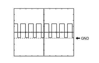
11 to 14 V G43-22 (BLW) - G43-14 (GND) L - W-B Blower motor speed control signal
-
Power switch on (IG)
-
Blower switch LO
Pulse generation
(See Waveform 2)
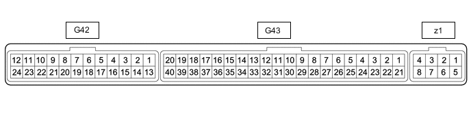
G43-23 (WP) - G43-14 (GND) P - W-B Heater water pump operation signal
-
Power switch on (IG)
-
Temperature settings MAX HOT
-
Blower switch LO
Pulse generation
(See Waveform 3)
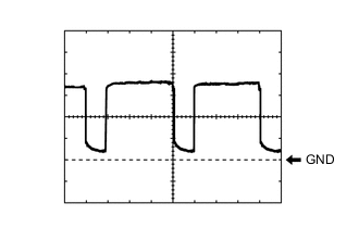
G43-24 (WIP) - G43-14 (GND) V - W-B Heater water pump condition signal
-
Power switch on (IG)
-
Temperature settings MAX HOT
-
Blower switch LO
Pulse generation
(See Waveform 4)
G43-27 (IDH) - G43-14 (GND) R - W-B Inverter with converter assembly current over signal
-
Power switch on (IG)
-
Quick heater assembly operation permitted
Below 1 V
-
Power switch on (IG)
-
Quick heater assembly operation not permitted
4.75 to 5.25 V G43-28 (RH) - G43-35 (SG-4) L - R Glass humidity sensor signal
-
Power switch on (IG)
-
Cabin temperature: 25°C (77°F)
-
Glass humidity: 60%
2.45 V
-
Power switch on (IG)
-
Cabin temperature: 25°C (77°F)
-
Glass humidity: 40%
1.97 V G43-29 (TR) - G43-34 (SG-1) V - L Room temperature sensor signal
-
Power switch on (IG)
-
Cabin temperature: 25°C (77°F)
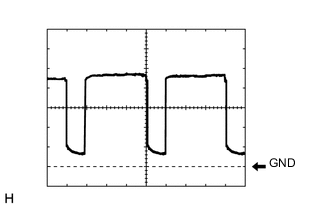
1.8 to 2.2 V G43-31 (S5-4) - G43-14 (GND) W - W-B Power source of room humidity sensor Power switch on (IG) 4.75 to 5.25 V G43-34 (SG-1) - Body ground L - Body ground Ground for room temperature sensor Always Below 1 Ω G43-35 (SG-4) - Body ground R - Body ground Ground for room humidity sensor Always Below 1 Ω z1-2 (BUS G) - Body ground - Ground for BUS IC Always Below 1 Ω z1-3 (BUS) - z1-2 (BUS G) - BUS IC control signal Power switch on (IG) Pulse generation
(See Waveform 5)
z1-4 (B BUS) - z1-2 (BUS G) - Power supply for BUS IC Power switch off 11 to 14 V z1-5 (SGA) - Body ground B - Body ground Ground for evaporator temperature sensor Always Below 1 V z1-6 (TEA) - z1-5 (SGA) GR - B Evaporator temperature sensor signal Power switch on (IG)
Evaporator temperature: 0°C (32°F)
1.7 to 2.1 V Power switch on (IG)
Evaporator temperature: 15°C (59°F)
0.9 to 1.3 V
-
*1: Value when the PTC heater is operating three
-
*2: Using a thermometer, to detects the ambient temperature around the installation area of the thermistor assembly is installed
-
-
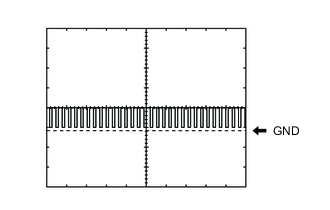
Waveform 1:
Item Content Terminal No. G42-22 (BLWH) - G43-14 (GND) Tool Setting 2 V/DIV., 500 μs/DIV. Vehicle Condition
-
Power switch on (IG)
-
Rear blower switch on
-
-
Waveform 2:
Item Content Terminal No. G43-22 (BLW) - Body ground Tool Setting 1 V/DIV., 500 μs/DIV. Vehicle Condition
-
Power switch on (IG)
-
Blower switch LO
-
-
Waveform 3:
Item Content Terminal No. G43-23 (WP) - G43-14 (GND) Tool Setting 5 V/DIV., 100 ms/DIV. Vehicle Condition
-
Power switch on (IG)
-
Temperature settings MAX HOT
-
Blower switch LO
-
-
Waveform 4:
Item Content Terminal No. G43-24 (WIP) - G43-14 (GND) Tool Setting 5 V/DIV., 100 ms/DIV. Vehicle Condition
-
Power switch on (IG)
-
Temperature settings MAX HOT
-
Blower switch LO
-
-
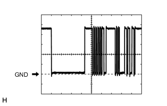
Waveform 5:
Item Content Terminal No. z1-3 (BUS) - z1-2 (BUS G) Tool Setting 2 V/DIV., 2 ms/DIV. Vehicle Condition Power switch on (IG)
-
-
INTEGRATION CONTROL AND PANEL ASSEMBLY

-
Disconnect the integration control and panel assembly connector.
-
Measure the resistance and voltage according to the value(s) in the table below.
Tech Tips
Check from the rear of the connector while it is connected to the integration control and panel assembly.
Terminal No.
(Symbol)
Wiring Color Terminal Description Condition Specified Condition G49-1 (+B) - G49-16 (GND) LG - W-B Power source (Back-up) Power switch off 11 to 14 V G49-9 (IG+) - G49-16 (GND) P - W-B Power source (IG) Power switch on (IG) 11 to 14 V Power switch off Below 1 V G49-16 (GND) - Body ground W-B - Body ground Ground for integration control and panel assembly Always Below 1 Ω -
Reconnect the integration control and panel assembly connector.
-
Measure the waveform according to the value(s) in the table below.
Tech Tips
Check from the rear of the connector while it is connected to the integration control and panel assembly.
Terminal No.
(Symbol)
Wiring Color Terminal Description Condition Specified Condition G49-4 (CANH) BR CAN communication line - - G49-5 (CANL) W CAN communication line - -
-
-
INSTRUMENT PANEL JUNCTION BLOCK ASSEMBLY, MAIN BODY ECU (MULTIPLEX NETWORK BODY ECU)
-
Remove the main body ECU (multiplex network body ECU) from the instrument panel junction block assembly.
-
for LHD: Click here
-
for RHD: Click here
-
-
Connect the instrument panel junction block assembly connectors.
-
Measure the voltage and resistance according to the value(s) in the table below.
Terminal No. (Symbol) Wiring Color Terminal Description Condition Specified Condition MB-32 (IG) - Body ground - Ignition power supply Power switch off Below 1 V Power switch on (IG) 11 to 14 V MB-31 (BECU) - Body ground - Auxiliary battery power supply Power switch off 11 to 14 V MB-30 (ACC) - Body ground - ACC power supply Power switch off Below 1 V Power switch on (ACC) 11 to 14 V MB-11 (GND1) - Body ground - Ground Always Below 1 Ω If the result is not as specified, there may be a malfunction in the wire harness or instrument panel junction block assembly.
-
Install the main body ECU (multiplex network body ECU).
-
for LHD: Click here
-
for RHD: Click here
-
-
Measure the voltage and pulse according to the value(s) in the table below.
Terminal No. (Symbol) Wiring Color Terminal Description Condition Specified Condition G6-13 (CANL) W CAN communication line - - G6-14 (CANH) BR CAN communication line - - G6-19 (CLTB) - G6-21 (CLTE) Y - BR Automatic light control sensor power supply output
-
Power switch on (IG)
-
Headlight dimmer switch in AUTO position
11 to 14 V G6-20 (CLTS) - G6-21 (CLTE) SB - BR Automatic light control sensor signal input Power switch on (IG), headlight dimmer switch in AUTO position and automatic light control sensor covered with a hand → Automatic light control sensor exposed to ambient light Pulse generation
(waveform varies depending on light volume)
(See Waveform 1)
G6-21 (CLTE) - Body ground BR - Body ground Ground for automatic light control sensor Always Below 1 Ω -
-
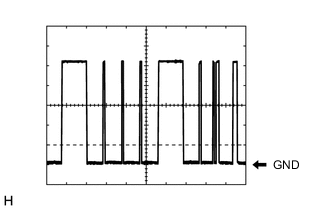
Waveform 1:
Item Content Terminal No. G6-20 (CLTS) - G6-21 (CLTE) Tool Setting 2 V/DIV., 10 ms/DIV. Vehicle Condition Power switch on (IG), headlight dimmer switch in AUTO position and automatic light control sensor covered with a hand → Automatic light control sensor exposed to ambient light
-
-
EV CONTROL ECU