AIR CONDITIONING SYSTEM SYSTEM DESCRIPTION
-
GENERAL
-
The air conditioning system has the following controls.
Control Function Neural Network Control This control is capable of performing complex control by artificially simulating the information processing method of the nervous system of living organisms in order to establish a complex input/output relationship that is similar to a human brain. Outlet Air Temperature Control Based on the temperature set by the temperature control switch, the neural network control calculates the outlet air temperature based on the input signals from various sensors. The temperature setting for the driver and front passenger is controlled independently in order to provide a separate vehicle interior temperature for the right and left sides of the vehicle. Thus, air conditioning control that accommodates occupant preferences has been achieved. Blower Control Controls the blower motor in accordance with the airflow volume that has been calculated by neural network control based on the input signals from various sensors. Automatically increases the blower level when the defroster is on. Air Outlet Control Automatically switches the air outlets in accordance with the outlet mode that has been calculated by neural network control based on the input signals from various sensors. In accordance with the FC coolant temperature, outside air temperature, amount of sunlight, required blower, outlet temperature and vehicle speed conditions, this control automatically switches the blower outlet to FOOT/DEF mode to prevent the windows from becoming fogged when the outside air temperature is low. Air Inlet Control Automatically controls the air inlet control damper to achieve the calculated outlet air temperature that is required. Drives the No. 1 blower damper servo sub-assembly (fresh/recirculation damper) in accordance with the operation of the air inlet control switch and moves the dampers to the FRESH or RECIRC position. Compressor Control The air conditioning amplifier assembly calculates the target speed of the compressor based on the target evaporator temperature (which is calculated by the room temperature sensor, ambient temperature sensor and solar sensor) and the actual evaporator temperature that is detected by the evaporator temperature sensor in order to control the compressor speed. Turns the air conditioning on automatically when the AUTO button is pressed when the blower is on and the air conditioning is OFF. Decreases the compressor speed in order to ensure quietness when the vehicle is stopped. PTC Heater Control When the power switch is turned on (IG) and the blower motor is turned on, the air conditioning amplifier assembly turns on the PTC heater (quick heater assembly) if the following conditions are met.
-
FC coolant temperature is below the specified temperature.
-
Ambient temperature is below the specified temperature.
-
Tentative air mix damper opening angle is above the specified value (MAX HOT).
Rear Window Defogger Control
-
Switches the rear defogger and outside rear view mirror heaters on for 15 minutes when the rear defogger and mirror heater switch is pressed.
-
Switches them off if the button is pressed while they are operating.
Windshield Deicer Control Switches the windshield deicer on for approx. 15 minutes when the windshield deicer switch is pressed. Turns on when the hybrid system is started while the outside temperature is low, and turns off after approx. 15 minutes automatically. Outside Temperature Indication Control Based on the signals from the thermistor assembly, this control calculates the outside temperature, and this value is then corrected in the air conditioning amplifier, and shown on the multi-information display. ECO Drive Mode Control When set to ECO drive mode, the air conditioning amplifier assembly decreases the blower speed. Diagnosis A Diagnostic Trouble Code (DTC) is stored in memory when the air conditioning amplifier assembly detects a problem with the air conditioning system. -
-
-
MODE POSITION AND DAMPER OPERATION
-
Mode Position and Damper Operation
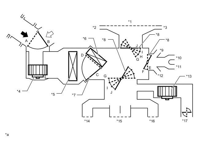
*1 Front Defroster *2 Driver Side Defroster *3 Front Passenger Side Defroster *4 Blower Motor with Fan Assembly *5 No. 1 Cooler Evaporator Sub-assembly *6 Air Conditioning Radiator Sub-assembly *7 Air Mix Control Door *8 Mode Switching Door *9 Front Passenger Side Footwell Register *10 Front Passenger Side Rear Footwell Register *11 Driver Side Rear Footwell Register *12 Driver Side Footwell Register *13 Cooler Blower Assembly *14 Driver Side Register *15 Center Register *16 Front Passenger Side Register *17 Console Box Duct No. 4 - - *a This illustration is a model diagram showing the damper positions in each mode. The parts layout and the number of the dampers in the illustration are different from those of the actual system. - - 
Fresh Air 
Recirculated Air Mode Position and Door Operation Control Door Operation Position Door Position Operation Air Inlet Control Door FRESH B Brings in fresh air. RECIRCULATION A Recirculates internal air. Air Mix Control Door HI - LO C - D Varies the mixture ratio of the hot air and the cool air in order to regulate the temperature continuously from HI to LO. Mode Control Door FACE E, J Air blows out of the front center register, side register. BI-LEVEL F, J Air blows out of the front center register, side register, console rear face register and front and rear footwell register ducts. FOOT F, I Air blows out of the front footwell register, rear footwell register and front register ducts. In addition, air blows out slightly from the front defroster. FOOT/DEF F, H Defrosts the windshield through the front defroster. At the same time, air is blown out from the footwell register, rear footwell register, the side register. DEF E, G Defrosts the windshield through the front defroster and side defroster. A small amount of air also blows out from the side register.
-
-
AIR OUTLETS AND AIRFLOW VOLUME
-
Air Outlets and Airflow Volume
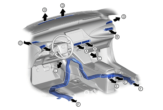
MODE A B C D E F Center Register Side Register Front Footwell Defroster Console Rear Face Register Rear Footwell 
FACE 
- - - 
BI-LEVEL 
- 
FOOT - 
- 
FOOT/DEF - - 
DEF - - - - The size of each circle ○ indicates the ratio of air flow volume.
-